
Light oil polluted unsaturated zone soil in-situ remediation apparatus and method thereof

An in-situ remediation and contaminated soil technology, applied in the restoration of contaminated soil, etc., can solve the problems of complex ground treatment system and excessive remediation function of light oil-contaminated soil

Active Publication Date: 2013-06-26
BC P INC CHINA NAT PETROLEUM CORP +1
View PDF12 Cites 13 Cited by
  • Summary
  • Abstract
  • Description
  • Claims
  • Application Information

AI Technical Summary

Problems solved by technology

[0004] At present, oil pollution remediation methods and devices are still based on ex-situ remediation, while in-situ remediation methods often have complex ground treatment systems, which are redundant for light oil-contaminated soil remediation

Method used


Image

  • Light oil polluted unsaturated zone soil in-situ remediation apparatus and method thereof
  • Light oil polluted unsaturated zone soil in-situ remediation apparatus and method thereof
  • Light oil polluted unsaturated zone soil in-situ remediation apparatus and method thereof

Examples


Embodiment approach 1

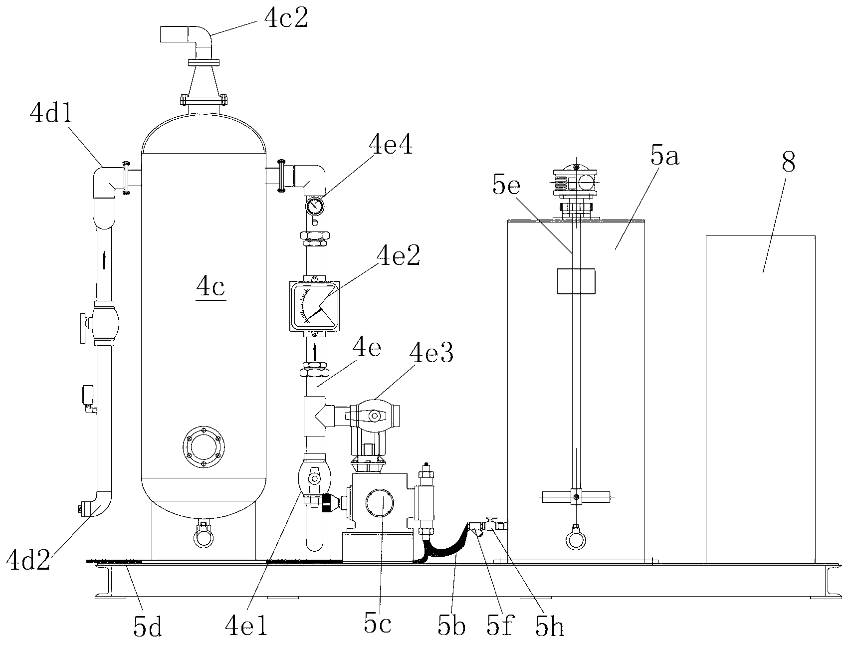
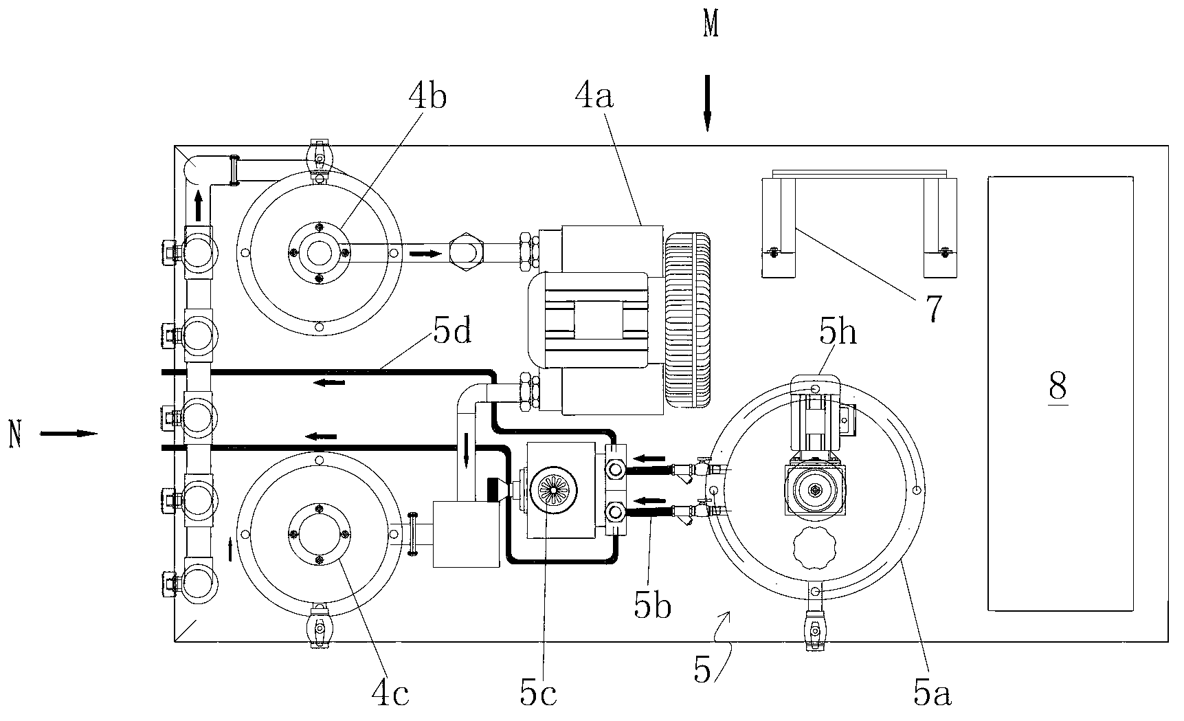
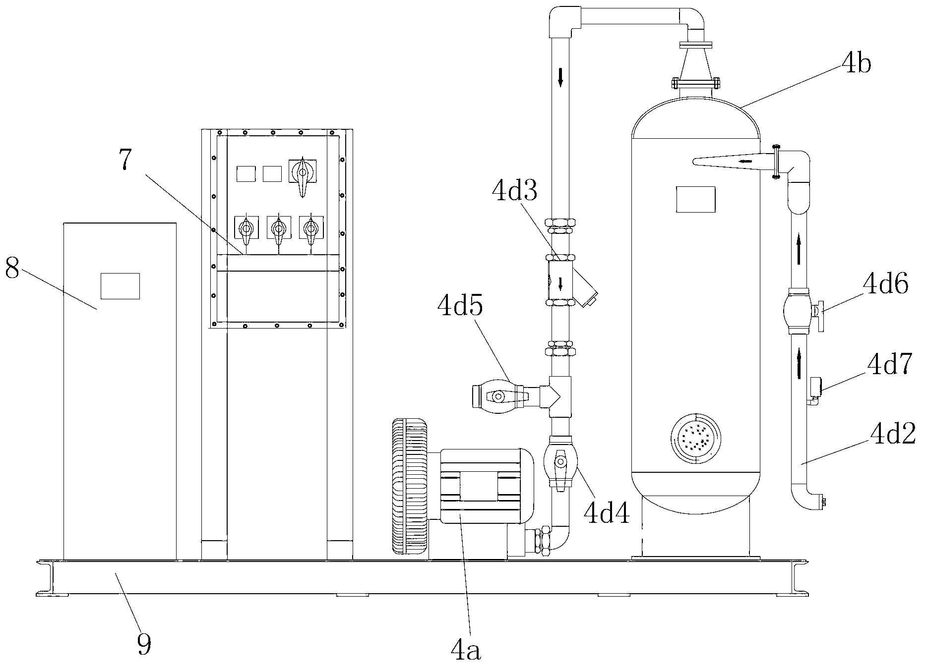
[0041] Such as Figure 1 to Figure 4 As shown, the embodiment of the present invention proposes an in-situ remediation device for light oil-contaminated soil, which includes a well group system, a soil suction system and a microbial remediation system. The well group system includes a suction well and a liquid injection well, the suction well 1 has a suction well head, and the liquid injection well 2 has a liquid injection well head, and the suction well head and the liquid injection well head are both 3 for the multifunctional well head. The soil suction system 4 includes a vortex vacuum pump 4a, an oil-gas separator 4b and an oil-gas adsorber 4c, the oil-gas separator 4b has a separation inlet pipe 4b1 and a separation air outlet pipe 4b2, and the oil-gas adsorber 4c has an adsorption inlet pipe 4c1 and adsorption air outlet pipe 4c2, the separated air inlet pipe 4b1 is connected to the suction well head through the suction pipe group 4d, the separated air outlet pipe 4b2 i...

Embodiment approach 2

[0067] A method for in-situ remediation of light oil-contaminated soil, said method comprising the steps of:

[0068] A. According to the on-site geological conditions of light oil-polluted soil, the distribution range and depth of pollutants, install the well group system, and determine the location and quantity of the suction well 1 and the injection well 2;

[0069] B. Operation of the soil suction system 4: turn on the vortex vacuum pump 4a, and the oil and gas in the soil, driven by negative pressure, enter the suction pipe group 4d through the suction well head; enter the suction pipe group 4d through the suction pipe group 4d After the oil and gas separator 4b removes moisture and soil particles, it enters the vortex vacuum pump 4a and turns to a positive pressure, and then enters the oil and gas adsorber 4c through the oil and gas delivery pipe 4e for purification and then discharges it into the atmosphere;

[0070] C. The operation of the microbial repair system 5: th...


PUM


Abstract

The invention relates to a light oil polluted unsaturated zone soil in-situ remediation apparatus and a method thereof. The apparatus comprises: a well group system which comprises a suction well, an injection well and a ventilation well, wherein the suction well has a suction well head, the injection well has an injection well head, and each of the suction well head and the injection well head is a multifunctional well head; a soil suction system which comprises a vortex vacuum pump, an oil-gas separator and an oil gas adsorber, wherein the oil gas separator has a separation gas inlet tube and a separation gas outlet tube, the oil gas adsorber has an adsorption gas inlet tube and an adsorption gas outlet tube, the separation gas inlet tube is connected with the suction well head through a suction tube group, the suction tube group is connected with the vortex vacuum pump, the separation gas outlet tube is connected with the adsorption gas inlet tube through an oil gas convey tube, and the adsorption gas outlet tube is communicated with the atmosphere; and a microbial remediation system which comprises a microbe and nutrient solution preparation tank, wherein an injection solution is contained in the microbe and nutrient solution preparation tank, the microbe and nutrient solution preparation tank is connected with the inlet of an injection metering pump through a solution suction pipeline, and the outlet of the injection metering pump is connected with the injection well head through an injection pipeline.

Description

technical field [0001] The present invention relates to the field of environmental protection, in particular to a supporting professional light oil-polluted soil in-situ remediation device and method for contaminated soil in gas stations, which integrates "soil gas phase suction", "biological ventilation" and "microorganism Strengthen technology" and other functions. Background technique [0002] Oil pollution refers to the pollution caused by crude oil or petroleum hydrocarbon products entering the environment due to various reasons during the process of oil extraction, processing, storage, transportation, and use. It is a negative product of the rapid development of the oil industry. Soil oil pollution in China is widely distributed in oil fields, refineries, and storage and transportation facilities, posing serious ecological and environmental risks. Compared with the development of soil pollution remediation technology in developed countries in the world, China still ha...

Claims


Application Information

Patent Timeline
Patent Type & Authority Applications(China)
IPC IPC(8): B09C1/00
Inventor 李巨峰许德刚张坤峰李金国冯涛李羽中
Owner BC P INC CHINA NAT PETROLEUM CORP
Learn More