Accuracy compensation method of coaxial macro-micro composite linear motion platform device

A technology of linear motion and platform device, which is applied to other manufacturing equipment/tools, large fixed members, metal processing machinery parts, etc., can solve the problems of high cost of motion platform device, large displacement amplitude of macro-motion platform, long time of stabilization process, etc. problem, to achieve the effect of improving the selection range, simple structure and low cost

Inactive Publication Date: 2015-06-03
SANYING MOTIONCONTORL TIANJIN INSTR CO LTD
View PDF13 Cites 1 Cited by
  • Summary
  • Abstract
  • Description
  • Claims
  • Application Information

AI Technical Summary

Problems solved by technology

The above-mentioned positioning device and method have achieved precise positioning of the PCB board, but the positioning device and method still have the following deficiencies: (1) The device uses a lead screw to drive the macro-motion platform to generate displacement, and the inherent crawling phenomenon of the lead screw itself It will cause a large displacement amplitude of the macro-moving platform from motion to rest, and it takes a long time to reach a stable process
However, in this solution, the grating ruler and the micro-motion sensor are used as the position accuracy detection in the coaxial direction, which requires that the grating ruler and the micro-motion sensor must achieve matching accuracy, resulting in increased costs and complicating the accuracy compensation method; The scheme uses air-floating guide rails, linear motors and other components, resulting in high cost and poor economy of the motion platform device, which limits its promotion scope

Method used


Image

  • Accuracy compensation method of coaxial macro-micro composite linear motion platform device

Examples


Embodiment

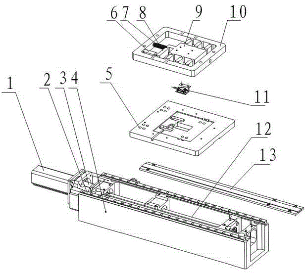
[0023] The overall structure schematic diagram of the present invention is as figure 1 As shown, the coaxial macro-micro compound linear motion platform device of the present invention includes a macro motion device, a micro motion device, a control device and a position detection device, wherein the macro motion device includes a servo driver 1, a linear drive module, and a linear guide rail 2 , the base 4 and the macro-motion working platform 5, the servo drive 1 is connected with the linear guide rail 2 through the linear drive module, the linear guide rail 2 is installed on the base 4, the macro-motion working platform 5 is installed on the linear guide rail 2, and the micro-motion device includes a high Precision micro-motion driver and flexible hinge amplification mechanism. The flexible hinge amplification mechanism includes a flexible hinge 8, a micro-motion working platform 9, and a frame 10, wherein the flexible hinge 8 is installed on the frame 10, and the micro-moti...


PUM


Abstract

The invention discloses a coaxial macro-micro composite linear motion platform device and an accuracy compensation method of the coaxial macro-micro composite linear motion platform device. The coaxial macro-micro composite linear motion platform device comprises a macro motion device, a micro motion device, a control device and a location detection device, wherein the macro motion device is composed of a servo driver, a straight line drive module, a straight line guide rail, a base and a macro moving working platform. The micro motion device is composed of a piezoelectric ceramic driver or a voice coil motor and a flexible hinge amplifying mechanism. The flexible hinge amplifying mechanism is composed of a flexible hinge, a micro motion working platform and a frame. The piezoelectric ceramic driver or the voice coil motor drives the flexible hinge amplifying mechanism to drive the micro motion working platform to generate displacement. The location detection device detects displacement information of a macro-micro motion working platform in real time and sends the displacement information to the control device. The control device drives the micro motion working platform to compensate motion of the macro motion device in real time according to detection information of a macro-micro motion displacement sensor, and thus high static accuracy and high dynamic accuracy of the coaxial macro-micro composite linear motion platform device are achieved.

Description

technical field [0001] The invention relates to an accuracy compensation method for a coaxial macro-micro composite linear motion platform device. Background technique [0002] With the development of society and the improvement of people's living conditions, people's requirements for products are getting higher and higher, which requires the manufacturing industry to continuously improve the processing accuracy of products. However, the range of high-precision feed motion platforms is generally short, and the accuracy of large-scale ordinary macro motion feed platforms cannot meet actual needs. If a dedicated large-scale high-precision motion platform is used, the manufacturing cost of the product will increase significantly. [0003] In view of the above-mentioned status quo, a motion platform that can realize large-scale and high-precision feeding, which can combine large-scale general-precision macro-motion and high-precision small-scale micro-motion, is more and more p...

Claims


Application Information

Patent Timeline
Patent Type & Authority Patents(China)
IPC IPC(8): B23Q1/34B23Q1/26B23Q17/24B23Q23/00
Inventor 杨志军白有盾陈新高健陈新度刘冠峰李克天李泽湘杨海东
Owner SANYING MOTIONCONTORL TIANJIN INSTR CO LTD
Why Eureka
Try Eureka