Single stand column plane coordinate mechanical arm of box filler

A technology of plane coordinates and robotic arms, which is applied in the direction of manipulators, program-controlled manipulators, chucks, etc., can solve the problems of cumbersome installation and adjustment, complex structure of robotic arms, and high production costs, so as to save time for replacement and installation and improve production efficiency , Simple structure and reliable effect

Active Publication Date: 2013-06-26
JIANGSU NEWAMSTAR PACKAGING MACHINERY
6 Cites 17 Cited by

AI-Extracted Technical Summary

Problems solved by technology

The mechanical arms in the four-link case packers, rocker arm case packers, and crank arm case packers commonly used in...

Method used

The advantage of the present invention is: adopt compressed air to extrude piston thereby inwardly extrude O-shaped spring 25, make it block the bottle-grasping mode of bottle mouth, be suitable for multiple bottle type, simple and reliable structure, the user need not according to different The bottle type is frequently replaced and the bottle-packing and grabbing mechanism is adjusted, which gre...

Abstract

The invention discloses a single stand column plane coordinate mechanical arm of a box filler. The single stand column plane coordinate mechanical arm of the box filler comprises a support stand column, a horizontal beam and a bottle grasping mechanical arm, wherein the support stand column and horizontal beam are perpendicularly arranged with each other. A lifting driving device capable of driving a lifting beam to move vertically is arranged on the support stand column. A translation driving device capable of driving the bottle grasping mechanical arm to move along the horizontal beam back and forth is arranged on the horizontal beam. A box-filling bottle-grasping mechanism with a plurality of grabs is arranged at the outer end of the bottle grasping mechanical arm. The structure of each grab comprises a support sleeve, a grab shell is arranged on the bottom portion of the support sleeve, a bottle grasping cavity with a horn-shaped bottle grasping opening is arranged inside the grab shell, a piston cavity is formed between the piston of the bottle grasping cavity and the bottle grasping cavity, the piston cavity is communicated with an air inlet channel, and an O-shaped spring is arranged on the inner wall of the grab shell on the top portion of the horn-shaped bottle grasping opening. After compressed air is injected into the air inlet channel, the piston can move downward until the bottom portion of the piston extrudes the outside of the O-shaped spring inwards to enable the inner ring of the O-shaped spring to be reduced and clamp the bottleneck of a bottle.

Application Domain

Technology Topic

Image

  • Single stand column plane coordinate mechanical arm of box filler
  • Single stand column plane coordinate mechanical arm of box filler
  • Single stand column plane coordinate mechanical arm of box filler

Examples

  • Experimental program(1)

Example Embodiment

[0013] The present invention will be described in further detail below in conjunction with the accompanying drawings and the preferred embodiments.
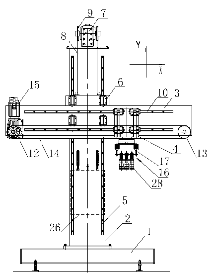
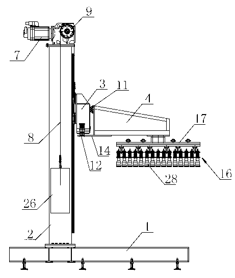
[0014] like figure 1 , figure 2 , image 3 As shown, the single-column plane coordinate mechanical arm on the cartoning machine includes a base 1, a support column 2 is fixedly installed on the base 1, a horizontal beam 3 is set on the support column 2, and a bottle grabbing mechanical arm 4 is set on the horizontal beam 3, The supporting column 2, the horizontal beam 3, and the bottle grabbing robotic arm 4 are perpendicular to each other, wherein the connection structure between the supporting column 2 and the horizontal beam 3 includes: the supporting column 2 is provided with a lifting guide 5, and the horizontal beam 3 is provided with The lifting slider 6 used in conjunction with the lifting guide 5, the supporting column 2 is provided with a lifting driving device, and the structure of the lifting driving device includes: a lifting servo motor 7 arranged on the top of the supporting column 2, and the output of the lifting servo motor 7 at both ends. A lift chain wheel 9 is respectively provided on the shaft, and a lift chain 8 is engaged and suspended on each lift chain wheel 9. One end of the two lift chains 8 is connected with the horizontal beam 3, and the other ends of the two lift chains 8 are respectively provided with The counterweight 26 is adapted to the weight of the horizontal beam 3. The provision of the counterweight 26 can reduce the output power of the lift servo motor 7, thereby reducing energy consumption. Driven by the lifting servo motor 7, the two lifting chains 8 can drive the horizontal beam 3 and the lifting slider 6 on the horizontal beam 3 to slide up and down along the lifting guide rail 5, and the two lifting chains 8 are used to lift the horizontal beam. 3 It is more stable and reliable during the lifting process. The connection structure between the horizontal beam 3 and the bottle grabbing mechanical arm 4 includes: a horizontal guide rail 10 is provided on the horizontal cross beam 3, the inner end of the bottle grabbing mechanical arm 4 is provided with a translation slider 11 used in conjunction with the horizontal guide rail 10, and the horizontal cross beam 3 is also provided with a translational drive device, and the structure of the translational drive device includes: the two ends of the horizontal beam 3 are respectively provided with an active synchronous pulley 12 and a driven synchronous pulley 13, and the active synchronous pulley 12 and the driven A synchronous belt 14 is provided on the synchronous pulley 13, one side of the synchronous belt 14 is fixedly connected with the bottom of the bottle grabbing mechanical arm 4, and a translation servo motor 15 is arranged on the horizontal beam 3 at the same end of the active synchronous pulley 12. , the active synchronous pulley 12 is driven by the translational servo motor 15. Under the drive of the translational servo motor 15, the bottle grabbing robot arm 4 and the translation slider 11 at the inner end of the bottle grabbing robot arm 4 can slide back and forth on the horizontal guide rail 10. A box-packing and bottle-grabbing mechanism 16 is provided at the outer end of the bottle-grabbing robot arm 4 , and the structure of the box-packing and bottle-grabbing mechanism 16 includes: a grasper mounting frame 17 installed at the bottom of the outer end of the bottle grasping robot arm 4 , and a grasper mounting frame 17 A number of grippers 28 are arranged on it. In this embodiment, three groups of grippers 28 are provided. Each group of grippers 28 is arranged in three rows, and five in each row are arranged. The number and arrangement of each group of grippers 28 can be set according to the size specification of a single box. The structure of a single gripper 28 includes: a support sleeve 18 mounted on the gripper mounting frame 17, an air intake passage 19 is provided through the support sleeve 18 from top to bottom, and a gripper shell 20 is provided at the bottom of the support sleeve 18 The inside of the grabbing shell 20 is provided with a bottle grabbing cavity 21 for accommodating the bottle head, the bottom of the grabbing shell 20 is provided with a trumpet-shaped bottle grabbing mouth 22 that communicates with the bottle grabbing cavity 21, and the top of the trumpet-shaped bottle grabbing mouth 22 is provided. An installation surface 201 is arranged on the inner wall of the grab shell 20, an O-shaped spring 25 is arranged on the installation surface 201, and an adjustment washer 202 is also arranged on the installation surface 201 at the bottom of the O-shaped spring 25. The height of the adjustment washer 202 can be adjusted according to different bottle types. For replacement, the bottle grabbing cavity 21 is provided with a piston 23 that can move up and down along the inner wall of the grabbing shell 20. A sealed piston cavity 24 is provided between the upper end of the piston 23 and the bottle grabbing cavity 21, and the piston cavity 24 is connected to the inlet and outlet. The air passage 19 communicates with each other. In order to ensure the sealing performance of the piston cavity 24, a sealing ring 27 is arranged in the piston cavity 24. The sealing ring 27 can move up and down along the inner wall of the grab shell 20 together with the piston 23 by being stuck in the groove on the top of the piston 23 . The bottom of the piston 23 is an inclined surface 231 inclined from the inside to the outside. After the compressed air is introduced into the intake passage 19, the piston 23 can move downward until the inclined surface 231 at the bottom of the piston 23 is squeezed to the outside of the O-shaped spring 25. Make its inner ring shrink and snap over the mouth of the bottle.
[0015] The working principle of the present invention is as follows: the direction of the horizontal beam 4 is the X direction, and the direction of the supporting column 2 is the Y direction. Start the lift servo motor 7, and the lift servo motor 7 drives the two lift sprockets 9 to rotate, thereby driving the two lift chains 8 to drive the horizontal beam 3 to move up or down along the lift guide 5, thereby changing the packing at the end of the bottle grabbing arm 4. The position of the bottle grabbing mechanism 16 in the Y direction; the translation servo motor 15 is activated, the translation servo motor 15 drives the active synchronous pulley 12 to rotate, and the synchronous belt 14 on the active synchronous pulley 12 drives the bottle grabbing robot arm 4 to come up on the horizontal guide rail 10 Sliding back to adjust the position of the packing and bottle grabbing mechanism 16 at the end of the bottle grabbing mechanical arm 4 in the X direction; through servo synchronization, the position of the packing and bottle grabbing mechanism 16 in the X and Y directions can be adjusted at the same time, so as to accurately realize The position of the packing and grabbing mechanism 16 in the plane is adjusted. During the packing work, it is only necessary to adjust the packing and bottle grabbing mechanism 16 to the corresponding position according to the position of the bottle, so that the bottle grabbing mouths 22 of each gripper 28 on the packing and bottle grabbing mechanism 16 are respectively fitted on the bottle head. Then, the compressed gas is introduced into the piston cavity 24 in each gripper, the pressure in each piston cavity 24 increases, and the sealing ring 27 and the piston 23 are pushed down until the slope 231 at the bottom of the piston 23 goes down Squeeze the outside of the O-shaped spring 25 to make the inner circle shrink and get stuck on the bottle mouth of the bottle. This way of grabbing the bottle is suitable for various bottle types; then adjust the packing by driving the lift servo motor 7 and the translation servo motor 15 The position of the bottle grabbing mechanism 16 in the X direction and the Y direction, so as to move the bottle grabbing mechanism 16 with the bottle clamped to the cartoning position, and make each group of grabbers 28 located on one case respectively, and then release The pressure in the piston cavity 24, under the action of atmospheric pressure, the piston 23 moves upward, thereby releasing the pressure on the O-shaped spring 25, and the O-shaped spring 25 recovers and deforms outward, thereby loosening the bottle mouth, so that each group of grippers The bottles in 28 fall into the corresponding empty boxes respectively, that is, the boxing is completed.
[0016] The advantages of the present invention are: using compressed air to squeeze the piston so as to squeeze the O-shaped spring 25 inwardly to make it jam the bottle mouth, it is suitable for a variety of bottle types, the structure is simple and reliable, and the user does not need to use different bottle types. Frequent replacement and adjustment of the packing and grabbing mechanism greatly saves the time for replacement and installation, thereby improving production efficiency; through the servo synchronization of the lift servo motor 7 and the translation servo motor 15, the movement of the packing and grabbing mechanism 16 can be accurately realized Positioning, and the bottle grabbing mechanical arm 4 runs stably and reliably during the movement of grabbing the bottle and packing it.

PUM

no PUM

Description & Claims & Application Information

We can also present the details of the Description, Claims and Application information to help users get a comprehensive understanding of the technical details of the patent, such as background art, summary of invention, brief description of drawings, description of embodiments, and other original content. On the other hand, users can also determine the specific scope of protection of the technology through the list of claims; as well as understand the changes in the life cycle of the technology with the presentation of the patent timeline. Login to view more.

Similar technology patents

Suction base for intelligent nursing toilet bowl

ActiveCN104382519AReliable structureAutomatically adjusts for comfortBathroom accessoriesTraffic volumeSpray nozzle
Owner:CRRC SHANDONG CO LTD

Classification and recommendation of technical efficacy words

Why Eureka
Try Eureka