Five-composite rubber extrusion head

A technology of extruder head and compound rubber, applied in the field of rubber machinery, can solve problems such as need to redesign, achieve the effect of optimized layout, reduced manufacturing and processing costs, good rigidity and strength

Active Publication Date: 2013-06-26
GUILIN RUBBER DESIGN INST
View PDF5 Cites 3 Cited by
  • Summary
  • Abstract
  • Description
  • Claims
  • Application Information

AI Technical Summary

Problems solved by technology

Although there are four compound rubber extruder heads now, in order to make the structure of the five compound rubber extruder unit with one extruder more compact and the layout reasonable, the extrusion ports of the five compound rubber extruder heads The size of

Method used


Image

  • Five-composite rubber extrusion head

Examples


Example Embodiment

[0028] Example 1

[0029] In this example, a five-compound rubber extruder unit equipped with five rubber extruders is taken as an example. The five rubber extruders are 120, 150, 250, 250, and 150 respectively, that is, the extruder screw diameter They are 120mm, 150mm, 250mm, 250mm, and 150mm respectively.

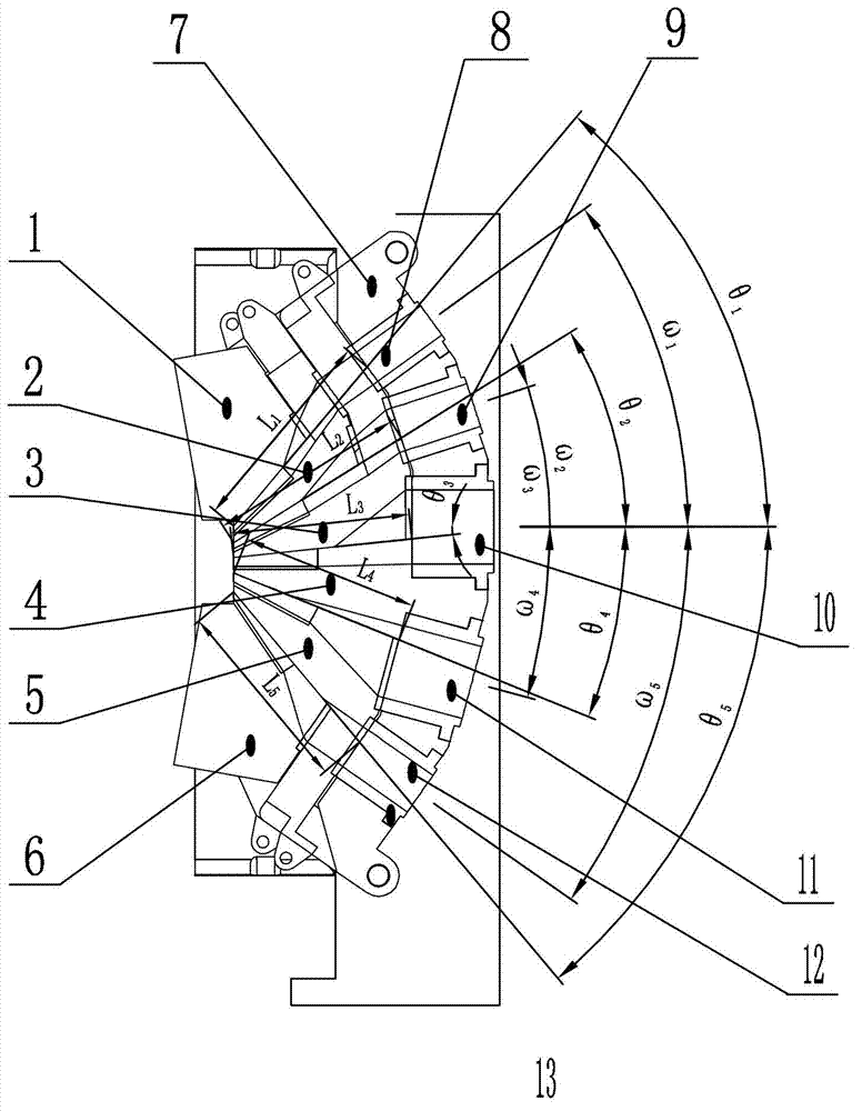
[0030] figure 1 Shown in this example is the five compound rubber extruder head of the five compound rubber extruder unit, including upper die 1, upper middle die 1, upper middle die 2 3, middle die 4, lower middle die 5, and lower die 6. The middle mold 4 and the mold base 7 are connected as a whole, the upper middle mold 4 is followed by upper middle mold two 3, upper middle mold one 2, and upper mold 1, upper middle mold two 3, upper middle mold 1, 2, and upper mold 1 The hinge shaft is hinged with the middle mold 4. Below the middle mold 4 are the lower middle mold 5 and the lower mold 6 in sequence, and the middle and lower molds 5 and 6 are hinged with the middle mold...

Example Embodiment

[0039] Example 2

[0040] This example is structured as figure 1 As shown, it is similar to Embodiment 1, except that the installation angles of each extrusion port and parting surface of the mold body and the length of each runner cavity are different from Embodiment 1.

[0041] The installation angle of each extrusion port in this example is: the included angle ω between the axis of the upper die extrusion port 8 and the horizontal plane 1 Is 45°, the angle between the axis of the upper and middle die 9 and the horizontal plane ω 2 Is 20°, the included angle ω between the axis of the middle die extrusion port 10 and the horizontal plane 3 Is -5°, the included angle ω between the axis of the lower middle die extrusion port 11 and the horizontal plane 4 Is -20°, the angle between the axis of the lower die extrusion port 12 and the horizontal plane ω 5 Is -45°.

[0042] The angle between the parting surface and the horizontal plane between the upper mold 1 and the upper middle mold 2 ...

Example Embodiment

[0044] Example 3

[0045] This example is structured as figure 1 As shown, it is similar to Embodiment 1, except that the installation angles of each extrusion port and parting surface of the mold body and the length of each runner cavity are different from Embodiment 1.

[0046] The installation angle of each extrusion port in this example is: the included angle ω between the axis of the upper die extrusion port 8 and the horizontal plane 1 Is 34°, the angle between the axis of the upper and middle die extrusion 9 and the horizontal plane ω 2 16°, the included angle ω between the axis of the middle die extrusion port 10 and the horizontal plane 3 2°, the included angle ω between the axis of the lower middle die extrusion port 11 and the horizontal plane 4 Is -13°, the angle ω between the axis of the lower die extrusion port 12 and the horizontal plane 5 Is -33°.

[0047] The angle between the parting surface and the horizontal plane between the upper mold 1 and the upper middle mold...


PUM

PropertyMeasurementUnit
Lengthaaaaaaaaaa
Lengthaaaaaaaaaa
Lengthaaaaaaaaaa

Abstract

The invention discloses a five-composite rubber extrusion head which comprises an upper die, a first upper-middle die, a second upper-middle die, a middle die, a lower-middle die and a lower die which are installed on a die base, wherein five extrusion ports which are connected with an extrusion cylinder and are arranged in a ride-back type structure are formed in the die base; and the extrusion ports which are arranged in an tilting manner are communicated with parting surface flowing chambers among the dies after die joint. The included angles among the axes and horizontal surfaces of the upper die extrusion port, the upper-middle die extrusion port, the middle die extrusion port, the lower-middle die extrusion port and the lower die extrusion port are respectively 30 degrees to 45 degrees, 10 degrees to 20 degrees, 5 degrees to -5 degrees, -10 degrees to -20 degrees, -30 degrees to -45 degrees, and preferably 34 degrees to 38 degrees, 16 degrees to 20 degrees, 2 degrees to -2 degrees, -13 degrees to -17 degrees and -33 degrees to -37 degrees; and the included angles among the parting surfaces and the horizontal surfaces of the dies and the lengths of the parting surface flowing chambers among the dies in match are also provided. The five-composite rubber extrusion head ensures the reasonable position of a linked extruder, optimizes the arrangement, and is convenient to install and maintain.

Description

Technical field [0001] The invention relates to a rubber machine, in particular to a five-compound rubber extruder head. Background technique [0002] In the existing tire production, generally speaking, most of the tread / sidewall semi-products are produced with two compound extrusion units and three compound extrusion units. There are also some high-grade tread / sidewall semi-products. Four compound extruders are used for production, but some of the treads / sidewalls produced by the two, three, and four compound extruders need to be film-laminated outside the machine. The dimensional accuracy of this kind of external bonding can no longer meet the dimensional accuracy and dynamic balance requirements of modern high-grade radial tires. Therefore, the development of a five-composite extrusion unit with more compound layers in the machine has become a high-end market demand. [0003] Five-compound rubber extruder unit changes the existing tire production in-machine compounding plus p...

Claims


Application Information

Patent Timeline
IPC IPC(8): B29C47/12B29C48/30
CPCB29C48/07B29C48/18B29C48/272B29C48/304B29C48/49B29K2021/006B29D30/72B29D2030/724
Inventor 黄发国江建平邓文忠程一祥王东明潘家芳
Owner GUILIN RUBBER DESIGN INST
Why Eureka
Try Eureka