
Automatic hydraulic rock breaking pick

A rock-breaking and hydraulic technology, which is applied in the field of self-controlled hydraulic rock-breaking picks, can solve problems such as difficult cooling of picks, affecting the efficiency of the working face, and difficult control of jet flow, so as to eliminate the lag of ejection time and eliminate the easy clogging of nozzles , the effect of reducing traffic consumption

Active Publication Date: 2015-04-22
CHINA UNIV OF MINING & TECH
View PDF5 Cites 0 Cited by
  • Summary
  • Abstract
  • Description
  • Claims
  • Application Information

AI Technical Summary

Problems solved by technology

[0002] At present, ordinary pick-shaped picks cut high-hardness rocks, which have problems such as large dust, sparks that are prone to explosion, difficulty in cooling the picks, and large wear. It is better to use high-pressure water jets and ordinary pick-shaped picks to crush hard rocks. Methods
However, in the prior art, the nozzle and the pick are arranged separately. Due to the influence of factors such as the installation position of the pick of the mining machine, the target distance of the nozzle, and the pressure, the high-pressure water jet cannot effectively act on the broken crack of the pick, and the energy loss is large. , cannot meet the requirements of high-efficiency and low-consumption crushing and the best dust removal effect, and it is difficult to control the jet flow in the downhole, and it is easy to form floods in the downhole, which affects the efficiency of the working face

Method used


Image

  • Automatic hydraulic rock breaking pick
  • Automatic hydraulic rock breaking pick
  • Automatic hydraulic rock breaking pick

Examples


Embodiment Construction

[0020] The present invention will be further explained below in conjunction with the accompanying drawings.

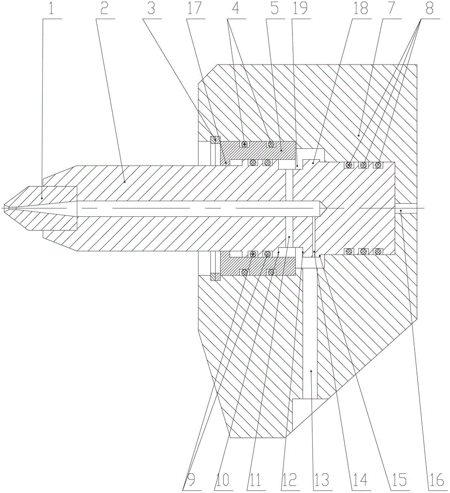
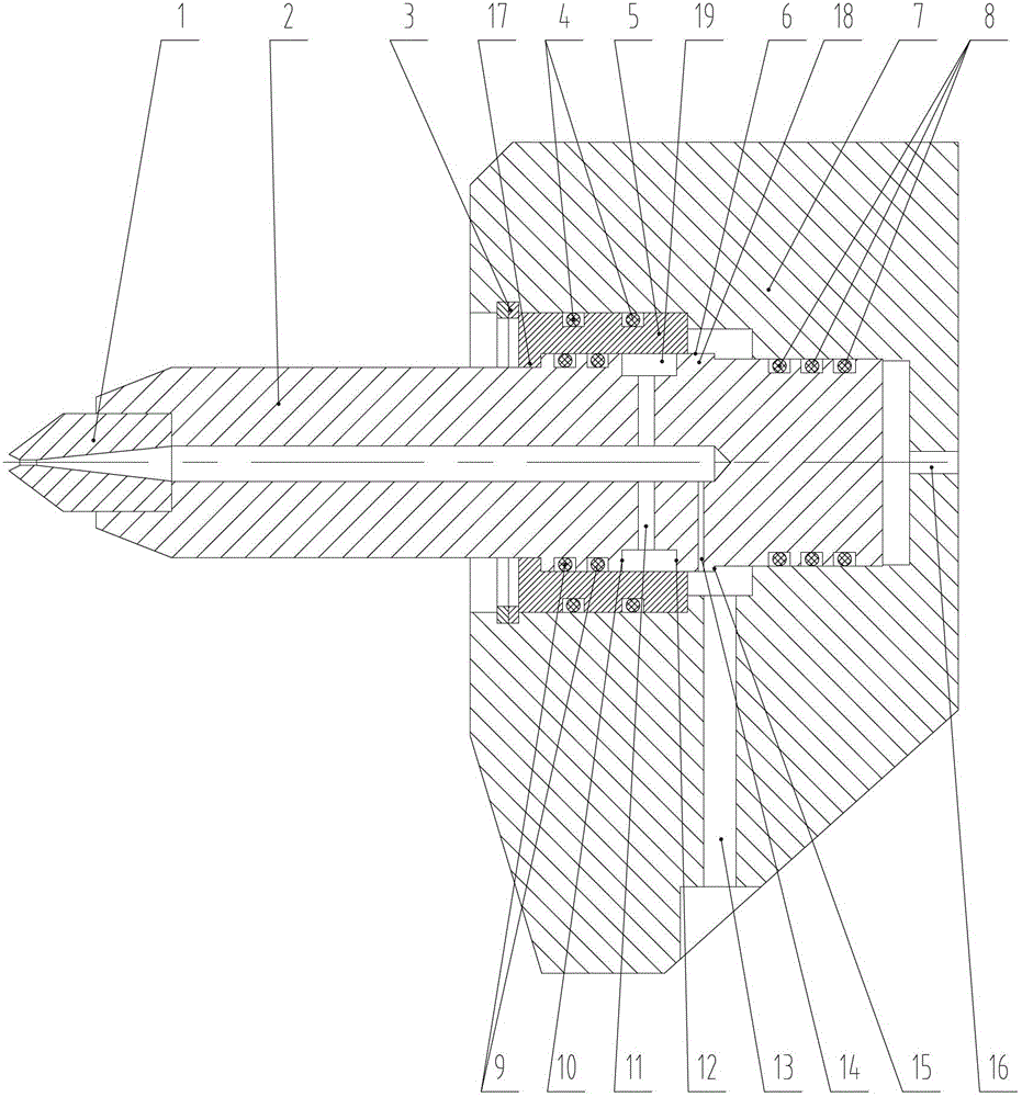
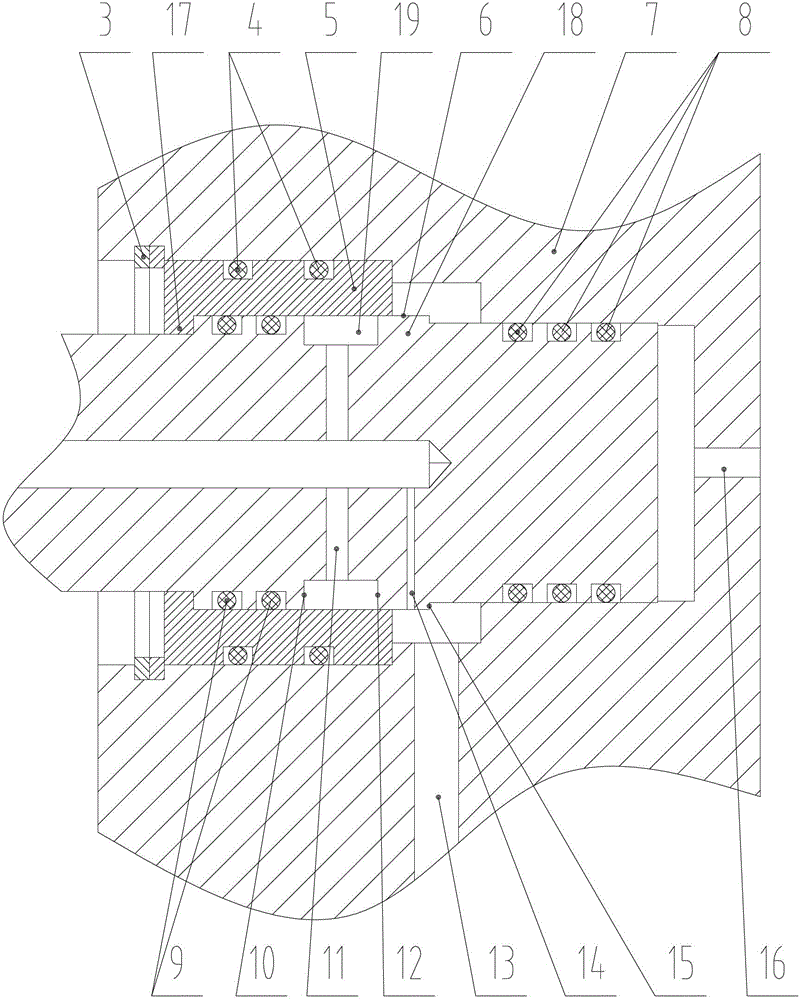
[0021] Such as Figures 1 to 3 As shown, the self-controlled hydraulic rock-breaking pick of the present invention includes a tip nozzle body 1, a tooth handle 2, a valve sleeve 5 and a tooth seat 7. The front end of the tooth handle 2 is welded to fix the tip nozzle body 1, and the tail end of the tooth handle 2 extends into the cavity of the tooth seat 7; the valve sleeve 5 is fixed in the cavity of the tooth seat 7 through the elastic retaining ring 3, and the inner wall of the valve sleeve 5 is close to the tooth handle 2 One side of the front end is provided with an annular protrusion 17; an annular shoulder 18 matching the valve sleeve 5 is provided at the tail end of the tooth handle 2, and an annular groove 19 is opened on the annular shoulder 18. The tip nozzle body 1 is provided with a spray hole in the axial direction, and the tooth handle 2 is provided wit...


PUM


Abstract

The invention discloses an automatic hydraulic rock breaking pick. The pick comprises a pick handle, the front end of the pick handle is provided with a pick tip nuzzling body, the tail end of the pick handle stretches to the inner cavity a pick seat, a valve pocket is arranged in the inner cavity of the pick seat, an annular projection is arranged at one side of the inner wall of the valve pocket close to the front end of the pick handle, the tail end of the pick handle is provided with an annular shaft shoulder adapted to the valve pocket, and the annular shaft shoulder is provided with an annular groove; and the pick tip nuzzling body and the pick handle are axially provided with a spray orifice and a central channel which are mutually communicated respectively, the bottom of the annular groove is provided with a pick handle radial high-pressure water through hole along a radial direction, a micro-damping hole is arranged at one side of the annular shaft shoulder close to the tail end of the pick handle along a radial direction, the pick handle radial high-pressure water through hole and the micro-damping hole are respectively communicated with the central channel, and the pick seat is provided with a high-pressure water inlet hole along a radial direction. The pick allows high-pressure water jet to be directly sprayed from the pick tip, the jet flow to be controllable and the dust suppression effect to be good.

Description

technical field [0001] The invention relates to a self-controlled hydraulic rock-breaking pick, in particular to a self-control hydraulic rock-breaking pick suitable for high-pressure water jet coal shearers, tunneling machines and rock drilling machines. Background technique [0002] At present, ordinary pick-shaped picks cut high-hardness rocks, which have problems such as large dust, sparks that are prone to explosion, difficulty in cooling the picks, and large wear. It is better to use high-pressure water jets and ordinary pick-shaped picks to crush hard rocks. Methods. However, in the prior art, the nozzle and the pick are arranged separately. Due to the influence of factors such as the installation position of the pick of the mining machine, the target distance of the nozzle, and the pressure, the high-pressure water jet cannot effectively act on the broken crack of the pick, and the energy loss is large. , cannot meet the crushing requirements of high efficiency and ...

Claims


Application Information

Patent Timeline
Patent Type & Authority Patents(China)
IPC IPC(8): E21C35/187
Inventor 刘送永杜长龙陈俊锋崔新霞刘晓辉刘增辉
Owner CHINA UNIV OF MINING & TECH
Learn More