Automatic switchover shuttle valve

A technology of automatic switching and shuttle valves, applied in the direction of sliding valves, valve details, multi-way valves, etc., can solve the problems of increasing processing difficulty and achieve the effects of good exhaust effect, simple structure, and impact reduction

Active Publication Date: 2013-06-26
BEIJING AEONMED
View PDF5 Cites 3 Cited by
  • Summary
  • Abstract
  • Description
  • Claims
  • Application Information

AI Technical Summary

Problems solved by technology

[0003] The purpose of the present invention is to provide an automatic switching shuttle valve to solve the technical problem that the existing shuttle valve increases the processing difficulty in order to realize the discharge of residual gas

Method used


Image

  • Automatic switchover shuttle valve
  • Automatic switchover shuttle valve
  • Automatic switchover shuttle valve

Examples


Embodiment Construction

[0028] The embodiments of the present invention will be described in detail below with reference to the accompanying drawings, but the present invention can be implemented in many different ways defined and covered by the claims.

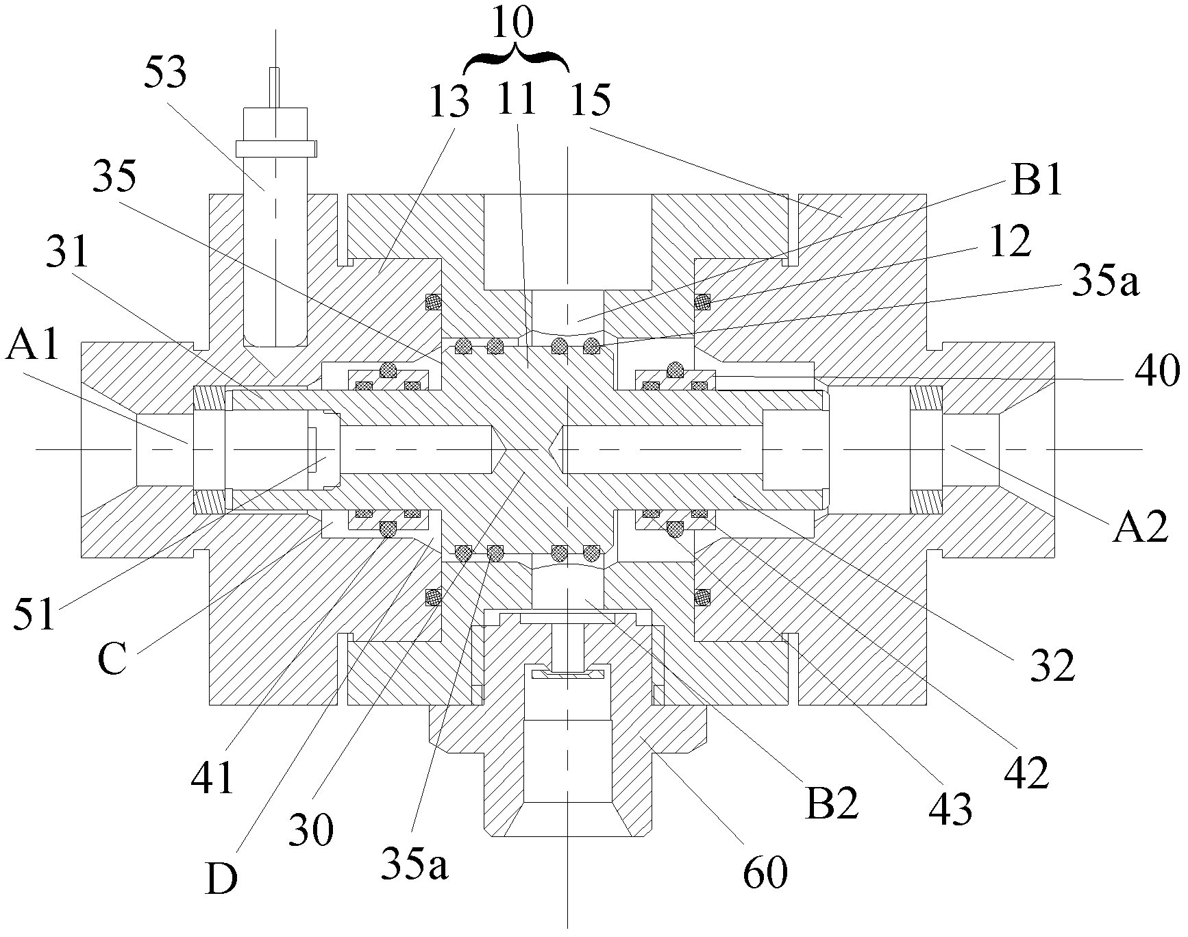
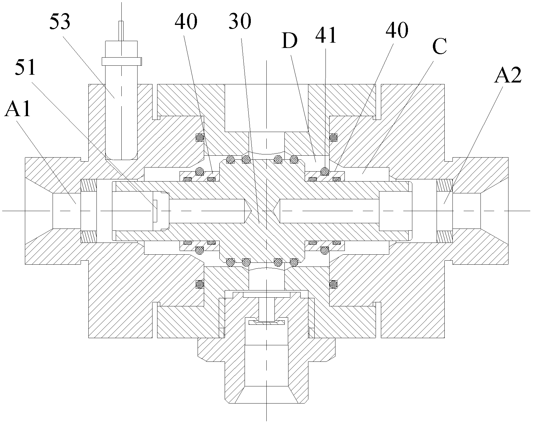
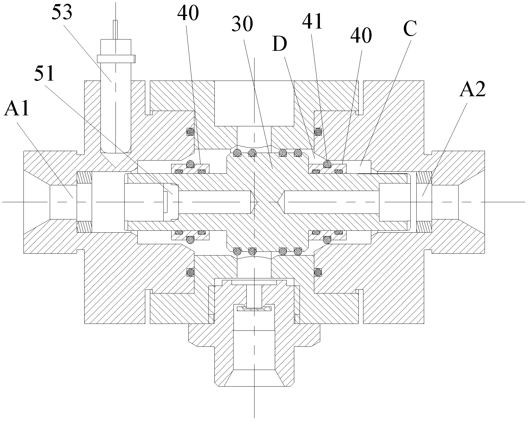
[0029] like figure 1 As shown, the present invention provides an automatic switching shuttle valve, including: a valve body 10 having a valve core moving chamber, and a first air inlet A1 and a second air inlet are formed on the side wall of the valve core moving chamber. Port A2 and the first air outlet B1, wherein the first air inlet A1 and the second air inlet A2 are oppositely arranged; the valve core 30 is located in the valve core moving cavity and has a first extension pointing to the first air inlet A1 The arm 31 and the second arm 32 pointing to the second air inlet A2, between the first arm 31 and the second arm 32 is provided with radially outwardly protruding and connected to the first air outlet B1 The opposite boss 35, wherein the out...


PUM


Abstract

The invention provides an automatic switchover shuttle valve which comprises a valve body and a valve element. The valve body is provided with a valve element mobile cavity. A first air inlet, a second air inlet and a first air outlet are formed in the sidewall of the valve element mobile cavity. The first air inlet and the second air inlet are oppositely arranged. The valve element is located in the valve element mobile cavity and is provided with a first extension arm pointing to the first air inlet and a second extension arm pointing to the second air inlet. A boss which protrudes outwards along the radial direction and is aligned with the first air outlet is arranged between the first extension arm and the second extension arm. Buffer sliding blocks are respectively arranged on the peripheries of the first extension arm and the second extension arm and can slide along the axis of the valve element. Through utilization of the buffer sliding blocks arranged on the peripheries of the extension arms, the automatic switchover shuttle valve can eliminate residual gas between the valve element and the valve body so that the valve element can be switched in place. Moreover, the automatic switchover shuttle valve is simple in structure, easy to realize and good in exhaust effects.

Description

technical field [0001] The invention relates to the field of shuttle valves, in particular to an automatic switching shuttle valve. Background technique [0002] When the automatic switching shuttle valve is switched, due to the movement and structural limitations of the shuttle body, a part of the residual gas will be compressed into a closed space. With the movement of the shuttle body, the volume of the closed space will be further reduced, and the residual gas in the space will Extreme pressure can be generated, preventing the normal operation of the main shuttle body. Usually, an exhaust gas discharge channel is set on the automatic switching shuttle valve of the gas valve box to discharge the residual gas. However, due to the limitation of the structure of the existing shuttle valve, it is necessary to process the exhaust channel to discharge the residual gas so that the shuttle body can be switched in place, which has great advantages. It is difficult to process, and...

Claims


Application Information

Patent Timeline
Patent Type & Authority Applications(China)
IPC IPC(8): F16K11/065F16K3/30F16K27/04
Inventor 韩玉崑
Owner BEIJING AEONMED
Why Eureka
Try Eureka