Dual polarized radiating dipole antenna

A dipole, dual-polarization technology, applied in the field of telecommunication antennas, can solve the problems of interfering radiating elements, etc., and achieve the effect of improving RF performance, reducing size and occupied space and width

Inactive Publication Date: 2013-06-26
ALCATEL LUCENT SAS
View PDF7 Cites 10 Cited by
  • Summary
  • Abstract
  • Description
  • Claims
  • Application Information

AI Technical Summary

Problems solved by technology

This configuration is too large for long dipole lengths and the external radiating element interferes with adjacent radiating elements

Method used


Image

  • Dual polarized radiating dipole antenna
  • Dual polarized radiating dipole antenna
  • Dual polarized radiating dipole antenna

Examples


Embodiment Construction

[0037] The elements contained in the drawings contribute to a better understanding of the description and contribute to the definition of the invention. In each of these figures, the same elements have the same reference numerals.

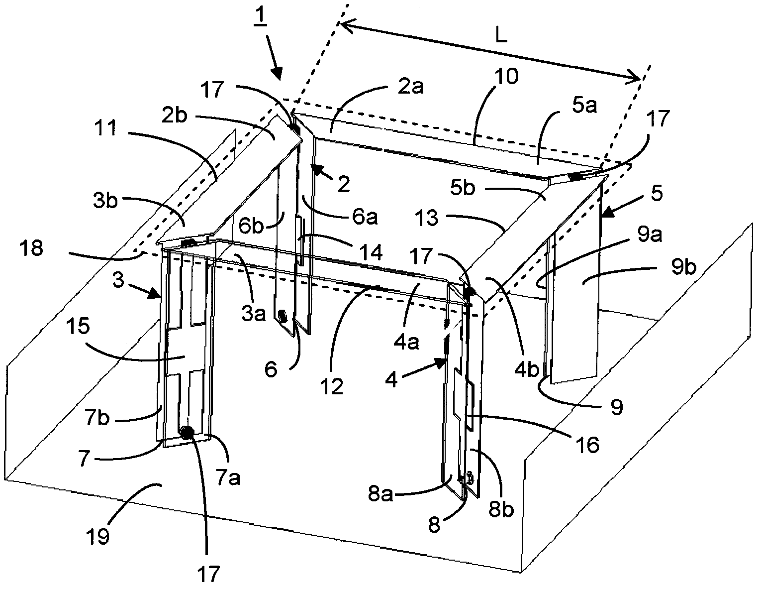
[0038] exist figure 1 In the embodiment described in, the radiating element 1 comprises four dipoles 2, 3, 4, 5. Each dipole 2, 3, 4, 5 comprises a bracket 6, 7, 8, 9, each bracket A pair of arms 2a, 2b; 3a, 3b; 4a, 4b; 5a, 5b are respectively supported. The two arms 2a, 2b; 3a, 3b; 4a, 4b; 5a, 5b of each dipole 2, 3, 4, 5 are oriented perpendicular to each other. Each bracket 6, 7, 8, 9 comprises two half brackets 6a, 6b; 7a, 7b; 8a, 8b; 9a, 9b, each half bracket having an inner side facing the other half bracket and an outer side side.

[0039] The collinear arms 2a and 5a belonging to the dipoles 2 and 5 respectively form a radiating strand 10 comprising a single straight conducting part, for example a thin metal sheet, elongated on each en...


PUM


Abstract

The dual polarised radiating element comprises four dipoles each comprising one stand and two arms. A first arm and a second arm belonging to two adjacent dipoles, form a straight radiating strand composed of a single part and the four radiating strands are arranged so as to form a disjoint square at the corners. The antenna comprises at least one first radiating element operating in a first frequency band and at least one second radiating element operating in a second frequency band and having at least one dipole that is arranged at the centre of the square formed by the radiating strands of the first radiating element, the radiating elements being arranged above a common reflector such that the transverse strands of the first radiating elements are located between two adjacent second radiating elements.

Description

[0001] Cross References to Related Applications [0002] This application is based on French patent application FR1058828 filed on October 27, 2010, the disclosure of which is hereby incorporated by reference in its entirety and claims priority based on 35 U.S.C. §119. technical field [0003] The invention relates to the field of telecommunication antennas using radiating elements for transmitting radio waves in the ultra-high frequency range. [0004] In particular, the invention relates to radiating elements to be operated in any frequency band, especially in the low frequency band of multi-band antennas, such as those found in telecommunication antennas. Such radiating elements can be used equally well in single-band antennas and in multi-band antennas known as patch antennas, especially intended for use in cellular telephone applications. Background technique [0005] Cellular telephones use various frequency bands corresponding to different known telecommunication sy...

Claims


Application Information

Patent Timeline
Patent Type & Authority Applications(China)
IPC IPC(8): H01Q21/24H01Q21/28H01Q15/16H01Q9/28H01Q1/24H01Q1/52
CPCH01Q1/246H01Q1/523H01Q9/285H01Q15/165H01Q21/24H01Q21/28H01Q11/14H01Q9/44H01Q9/16
Inventor J·普莱A·伊拉里G·科基耶T·朱利安G·福克雷
Owner ALCATEL LUCENT SAS
Why Eureka
Try Eureka