Straightening machine for electronic component lead

A technology of electronic components and straightening machines, which is applied in the field of electronic component lead wire straightening machines, can solve problems such as difficult quality control, lead wire stretching deformation, looseness, etc., and achieves the goal of improving production efficiency, avoiding pulling damage, and reasonable structural design Effect

Inactive Publication Date: 2013-07-03
SHANDONG DIYI ELECTRONICS SCI & TECH
View PDF8 Cites 6 Cited by
  • Summary
  • Abstract
  • Description
  • Claims
  • Application Information

AI Technical Summary

Problems solved by technology

[0002] At present, there is a large demand for semiconductor plastic-encapsulated electronic components. In the production process, there is a process of straightening the leads. Now most of them need to be straightened manually. Due to the low efficiency of manual straightening and the difficulty of quality control, it is seriously limited. The increase in the output of plastic-encapsulated electronic components directly affects the economic benefits of manufacturers
[0003] Although there are patents disclosing some lead wire straightening equipment, many of them use pulling lead wires to achieve the straightening effect, and the stretching deformation and loosening of the lead wires will be caused during the pulling process, which will affect the electrical indicators of the lead wires, and then affect the quality of electronic components.

Method used


Image

  • Straightening machine for electronic component lead
  • Straightening machine for electronic component lead
  • Straightening machine for electronic component lead

Examples


Embodiment Construction

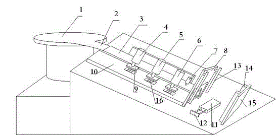
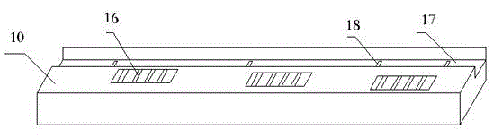
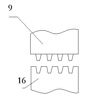
[0020] Such as figure 1 , 2 , 3 shows, a kind of electronic component lead wire straightening machine of the present invention, comprises controller, power unit, vibrating plate 1 and workbench, and vibrating plate 1 outlet is connected with transport piece flat rail 2. The electronic components are placed in the vibrating plate 1, and the electronic components are arranged and output from the flat rail 2 during the vibration process. The inner side of the workbench is horizontally provided with a chute 17 that is smoothly transitioned to the end of the conveying flat rail 2 . Generally, the bottom of the workbench is supported by a slope frame. The outside of the workbench is provided with a lead wire straightening platform 10, and a straightening mechanism is arranged on the lead wire straightening platform 10. A lifting lead lug 9 that can be clamped and matched with the lead wire slot is provided; a component stop mechanism that can stop the electronic component lead wi...


PUM


Abstract

The invention discloses a straightening machine for an electronic component lead, which comprises a controller, a power unit, a vibrating disk and a working platform, wherein an outlet of the vibrating disk is connected with a transporting part flat rail; a slide chute smoothly connected with the tail end of the transporting part flat rail in a transition manner is horizontally arranged on the inner side of the working platform; the transporting part flat rail and the slide chute are both high at the front and low in the rear, and inclined downwards; the transporting part flat rail is higher than the slide chute; a lead straightening platform is arranged on the outer side of the working platform and is provided with a straightening mechanism; the straightening mechanism comprises a lifting lead clamp groove formed in the straightening platform; a lifting lead bulged block capable of being mutually clamped and matched with the lead clamp groove is arranged at the opposite position above the lifting lead clamp groove; a component stop-limiting mechanism enabling the electronic component lead in the slide chute to stop in the risen lifting lead clamp groove is arranged on the working platform; and a material pipe is in butt joint with the tail end of the slide chute. The straightening machine for the electronic component lead has the benefits that the straightening effect is good, the tractive damage to the lead is prevented, and the automatic pipe arrangement is adopted, so that the production efficiency is improved greatly.

Description

technical field [0001] The invention relates to a straightening machine for lead wires of electronic components. Background technique [0002] At present, there is a large demand for semiconductor plastic-encapsulated electronic components. In the production process, there is a process of straightening the leads. Now most of them need to be straightened manually. Due to the low efficiency of manual straightening and the difficulty of quality control, it is seriously limited. The increase in the output of plastic-encapsulated electronic components directly affects the economic benefits of manufacturers. [0003] Although there are patents disclosing some lead wire straightening equipment, many of them use pulling lead wires to achieve the straightening effect, and the stretching deformation and loosening of the lead wires will be caused during the pulling process, which will affect the electrical indicators of the lead wires, and then affect the quality of electronic componen...

Claims


Application Information

Patent Timeline
Patent Type & Authority Applications(China)
IPC IPC(8): B21F1/02
Inventor 陈钢全
Owner SHANDONG DIYI ELECTRONICS SCI & TECH
Why Eureka
Try Eureka