
A kind of thin strip continuous casting free looper control method and device

A control method and looper technology, which are applied in the field of free looper control methods and devices for thin strip continuous casting, can solve problems such as cracks in overcasting strips, and achieve the benefits of looper control, accurate looper shape and position, and process adaptability. strong effect

Active Publication Date: 2015-08-26
BAOSHAN IRON & STEEL CO LTD +1
View PDF9 Cites 0 Cited by
  • Summary
  • Abstract
  • Description
  • Claims
  • Application Information

AI Technical Summary

Problems solved by technology

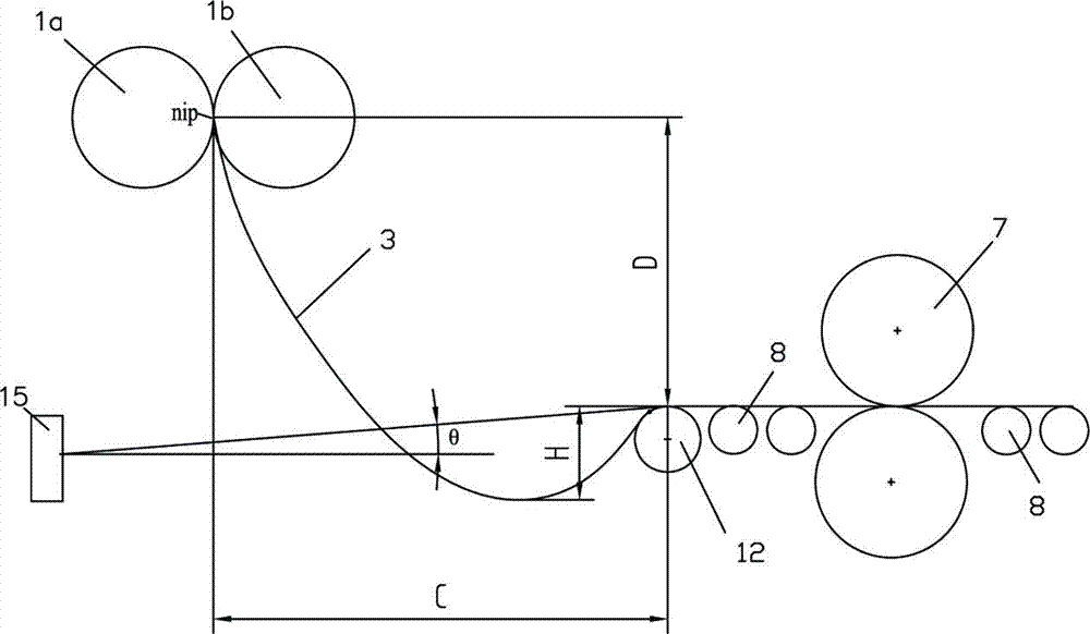
[0018] On the other hand, the increased loop height of the cast strip also results in a bend radius r at the bottom of the loop b becomes smaller, according to formula (4), if the bending radius of the cast strip here is too small, it will also cause cracks in the cast strip

Method used


Image

  • A kind of thin strip continuous casting free looper control method and device
  • A kind of thin strip continuous casting free looper control method and device
  • A kind of thin strip continuous casting free looper control method and device

Examples


Embodiment 1

[0054] see Figure 2 to Figure 7 , a thin strip continuous casting free looper control method of the present invention comprises the following steps:

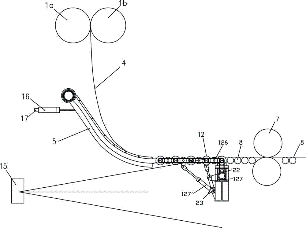
[0055] a. At the initial stage of casting, the swinging guide plate 5 is lifted and located at its upper working position, and the casting belt looper guide device 12 is lifted to keep the conveying height of the casting belt formed on the upper surface of all the rollers consistent with the height of the subsequent conveying roller table, The upper surface of the swing guide plate 5 borders on the most end roller surface of the cast belt looper guide 12, and keeps the height of the joint of the two consistent, as image 3 , the casting belt can be smoothly conveyed to the follow-up conveying roller table 8 through the swing guide plate and the loop guide device.

[0056] b. After the casting belt enters the follow-up process, the swing guide plate 5 swings to its lower working position. At this time, the cast strip loop guid...

Embodiment 2

[0069] see Figure 8 , the thin strip continuous casting free looper control method of the present invention comprises the following steps:

[0070] a. The casting belt establishes a looper, and the swing guide plate 5 swings to its lower working position under the drive of the hydraulic cylinder 16. The specific working position is detected by the displacement sensor 17 and fed back to the looper guide controller 18, which is passed through the servo valve. 19 implement the stroke control to the hydraulic cylinder.

[0071] b. At the same time, the looper detection device 15 monitors the height of the looper in real time, and outputs the detection value to the looper guide controller 18, and the looper position data detected on the power generation motors 126a-126d on the looper guide roller group 12 is output To the looper guide controller 18, the latter calculates the casting belt guide bending radius r according to the parameters such as the current casting belt looper he...


PUM

PropertyMeasurementUnit
diameteraaaaaaaaaa

Abstract

The invention discloses a control method and device for a thin-strip continuous casting free loop. The control device comprises a swing guide plate, a drive hydraulic cylinder of the swing guide plate, and a loop height detection device arranged on the outer side under the swing guide plate, wherein a displacement sensor is arranged on the swing guide plate; both the loop height detection device and the displacement sensor are electrically connected with a loop guide controller; the loop guide device is arranged in front of a horizontal conveying roller path and comprises a loop guide roller set with variable curvature and a corresponding drive hydraulic cylinder; a sensor capable of detecting position data of a loop contact point is arranged on the loop guide roller set; and the loop guide controller is electrically connected with a servo valve for driving the hydraulic cylinder. When the parameter such as the thickness, the loop height or the like of a cast strip is changed, the bending radius of the cast strip guide profile of the loop guide device can be adjusted to be greater than the minimal bending radius capable of leading the cast strip to generate cracks so as to guarantee the cast strip to have no cracks and obtain good quality of the cast strip.

Description

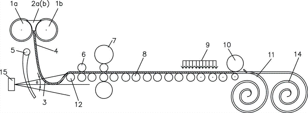
technical field [0001] The invention relates to a continuous casting process and equipment, in particular to a thin strip continuous casting free looper control method and device. Background technique [0002] Twin-roll strip continuous casting technology is an advanced short-flow metallurgical process. [0003] Such as figure 1 As shown, the molten steel is directly poured into a molten pool surrounded by two relatively rotating cooling rolls 1a, 1b capable of rapid cooling and side sealing plates 2a, 2b. Cool and solidify, and then form a solidified shell and gradually grow and then be squeezed together at the smallest gap between the two cooling rollers 1a and 1b to form a cast steel strip 4, which is guided by the guide plate 5 to the looper guide roller 12 and the clamp Send roll 6, and form looper 3 between looper guide roll 12 and cooling roll 1a, 1b, and then roll into thin strip by rolling mill 7, and the rolled strip is driven by conveying roller table 8 to under...

Claims


Application Information

Patent Timeline
Patent Type & Authority Patents(China)
IPC IPC(8): B22D11/06B22D11/16
Inventor 叶长宏韩月生方园张健郑群牛晋生
Owner BAOSHAN IRON & STEEL CO LTD
Learn More