
Welding tool and welding method of connecting plate

A technology of welding tooling and welding method, which is applied in the field of welding tooling and welding of connection plates, can solve the problems of high economic cost and multi-time cost of connection plates, achieve convenient adjustment and turning, reduce processing allowance, and improve welding efficiency Effect

Active Publication Date: 2019-11-12
WUHAN MARINE MACHINERY PLANT
View PDF5 Cites 2 Cited by
  • Summary
  • Abstract
  • Description
  • Claims
  • Application Information

AI Technical Summary

Problems solved by technology

[0003] When welding the annular cylinder and the annular flange plate, the annular flange plate will produce a certain welding deformation, so it is necessary to leave more machining allowance on the surface of the annular flange plate, so that the ring method can be corrected in the subsequent process. The surface of the flange plate is processed to make the surface of the ring flange plate relatively smooth, but there is more machining allowance left on the surface of the ring flange plate. The increase of the machining allowance will make the economic cost of the connection plate higher. , and it takes more time and cost to process more machining allowance

Method used


Image

  • Welding tool and welding method of connecting plate
  • Welding tool and welding method of connecting plate
  • Welding tool and welding method of connecting plate

Examples


Embodiment Construction

[0045] In order to make the object, technical solution and advantages of the present invention clearer, the embodiments of the present invention will be further described in detail below in conjunction with the accompanying drawings.

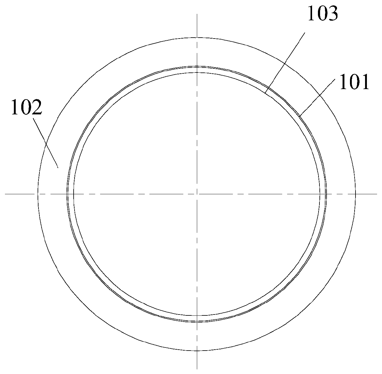
[0046] figure 1 is a schematic structural diagram of the land provided by the embodiment of the present invention, figure 2 It is a top view of the connection pad provided by the embodiment of the present invention. Can start with figure 1 and figure 2 To understand the specific structure of the connection plate in the book, it is convenient to understand the welding tooling of the connection plate in the following text.

[0047] combine figure 1 and figure 2 , the connection plate 10 may include an annular cylinder 101 , an annular flange plate 102 , and an annular rib plate 103 . One end of the annular cylinder 101 is welded on the annular flange plate 102 , the annular cylinder 101 is coaxial with the annular flange plate 102 , and t...


PUM


Abstract

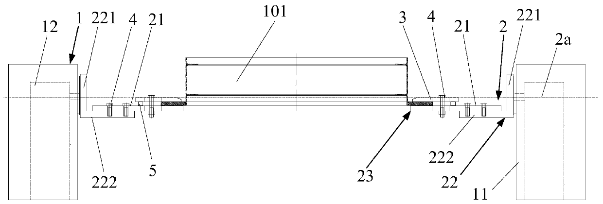
The invention discloses a welding tool and a welding method of a connecting plate, and belongs to the field of machining. When the connecting plate is welded, an annular cylinder, an annular flange plate and an annular rib plate are generally spot-welded and assembled, then the annular flange plate is placed on the supporting surfaces of two supporting structures, the annular flange plate is pressed by a pressing plate, the plate surface of the annular flange plate is clamped by the pressing plate and the supporting surface of the supporting structure of the welding tool, so that the positionof the annular flange plate is well fixed, the deformation generated in the welding process is small, therefore, the machining allowance reserved on the surface of the annular flange plate can be reduced, the material required for manufacturing the annular flange plate is reduced due to the reduction of the machining allowance, the machining allowance required for machining is also reduced, and the economic cost and the time cost for manufacturing the connecting plate are reduced. According to the two driving structures arranged at an interval in the welding tool, adjusting and overturning theposition of the connecting plate is convenient, so that the welding efficiency of the connecting plate is improved, and the time cost required by manufacturing the connecting plate is further reduced.

Description

technical field [0001] The invention relates to the field of mechanical processing, in particular to a welding tool and a welding method for a connecting plate. Background technique [0002] Currently there is a connecting plate, which includes an annular flange plate, an annular rib plate, and an annular cylinder. One end of the annular cylinder is welded on the annular flange plate, the annular cylinder and the annular flange plate are coaxial, and the annular rib plate is coaxially welded on the inner wall of the annular cylinder. [0003] When welding the annular cylinder and the annular flange plate, the annular flange plate will produce a certain welding deformation, so it is necessary to leave more machining allowance on the surface of the annular flange plate, so that the ring method can be corrected in the subsequent process. The surface of the flange plate is processed to make the surface of the ring flange plate relatively smooth, but there is more machining allo...

Claims


Application Information

Patent Timeline
IPC IPC(8): B23K37/053B23K31/02
CPCB23K31/02B23K37/053
Inventor 蒋文学杨新明赵金明
Owner WUHAN MARINE MACHINERY PLANT
Learn More