Method and device for positioning double-roller thin-strip continuous casting roller and adjusting roller gap

A twin-roll thin strip and adjustment method technology, which is applied in the field of continuous casting equipment, can solve the problems of casting strip deviation, the influence of detection accuracy, and the inability to perform curling and rolling, so as to ensure positioning accuracy, shorten adjustment time, and eliminate detection effect of influence

Active Publication Date: 2013-07-03
BAOSHAN IRON & STEEL CO LTD +1
View PDF8 Cites 18 Cited by
  • Summary
  • Abstract
  • Description
  • Claims
  • Application Information

AI Technical Summary

Problems solved by technology

And from image 3 It can be seen that since the fixed roll-casting roll 5a leans against the fixed stoppers 16a, 16b through the bearing seats on both sides, if the fixed roll-casting roll 5a on the two side stoppers is deflected relative to the casting centerline, the casting belt In the process of conveying to the coiler, deviation will occur. In severe cases, the casting belt will scrape and curl with the side guide plate, so that it cannot be crimped and rolled, and the casting cannot be carried out continuously.
[0007] In addition, if the bearing seat of the fixed roll-casting roll 5a is in contact with the fixed stoppers 16a, 16b, the force between them and the stoppers will indirectly affect the detection of the casting and rolling force. Accuracy can be greatly affected by

Method used


Image

  • Method and device for positioning double-roller thin-strip continuous casting roller and adjusting roller gap
  • Method and device for positioning double-roller thin-strip continuous casting roller and adjusting roller gap
  • Method and device for positioning double-roller thin-strip continuous casting roller and adjusting roller gap

Examples


Embodiment Construction

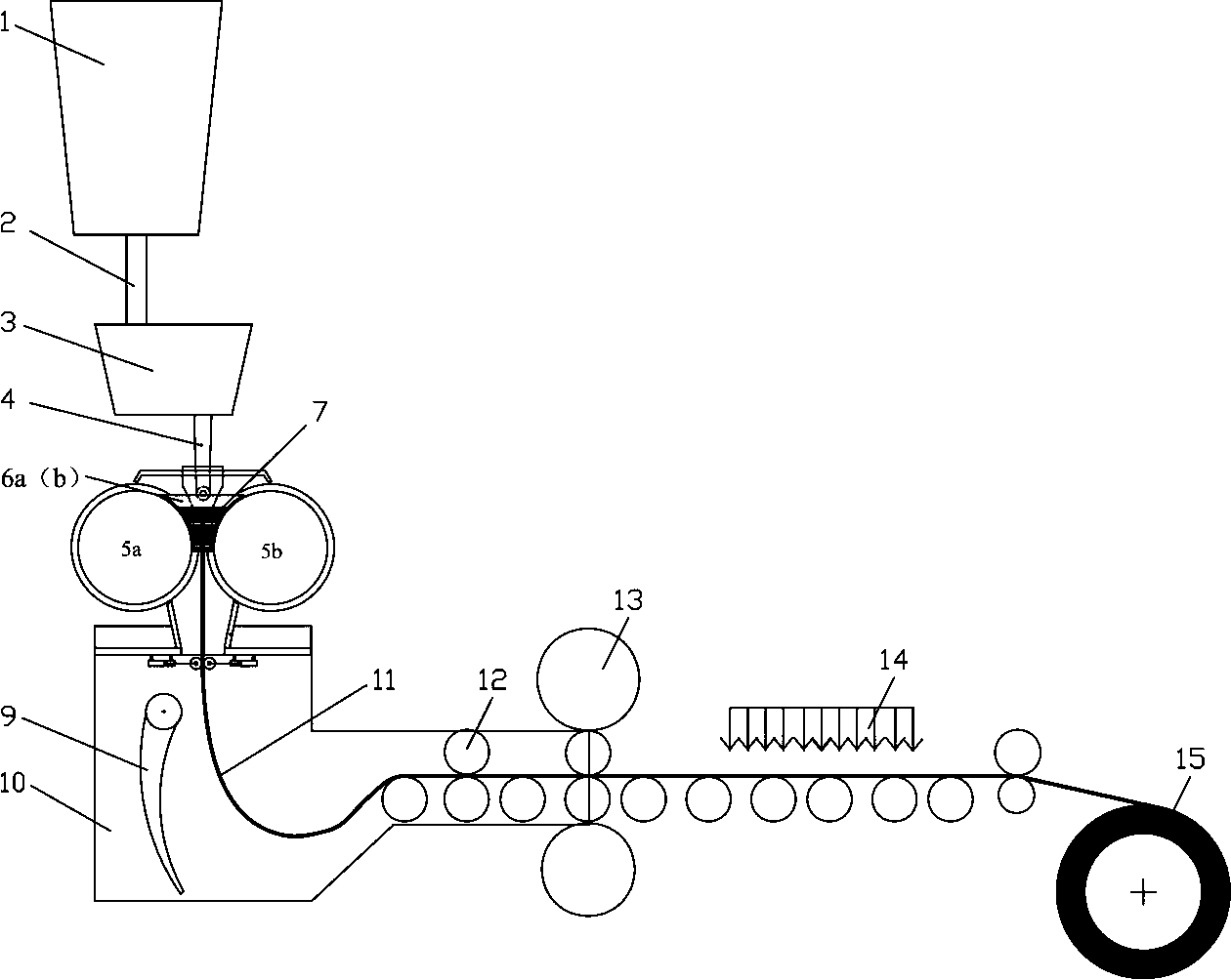
[0044] see Figure 1 to Figure 8 , the twin-roll strip continuous casting machine of the present invention comprises two relatively rotating cooling casting rolls 5a, 5b and side sealing plates 6a, 6b whose ends fit together, the molten steel in the ladle tundish passes through the nozzle cloth It flows into the molten pool 7 formed by the two and solidifies to form a steel strip.

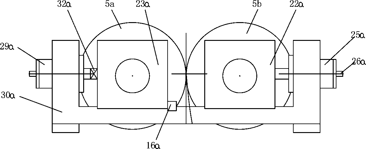
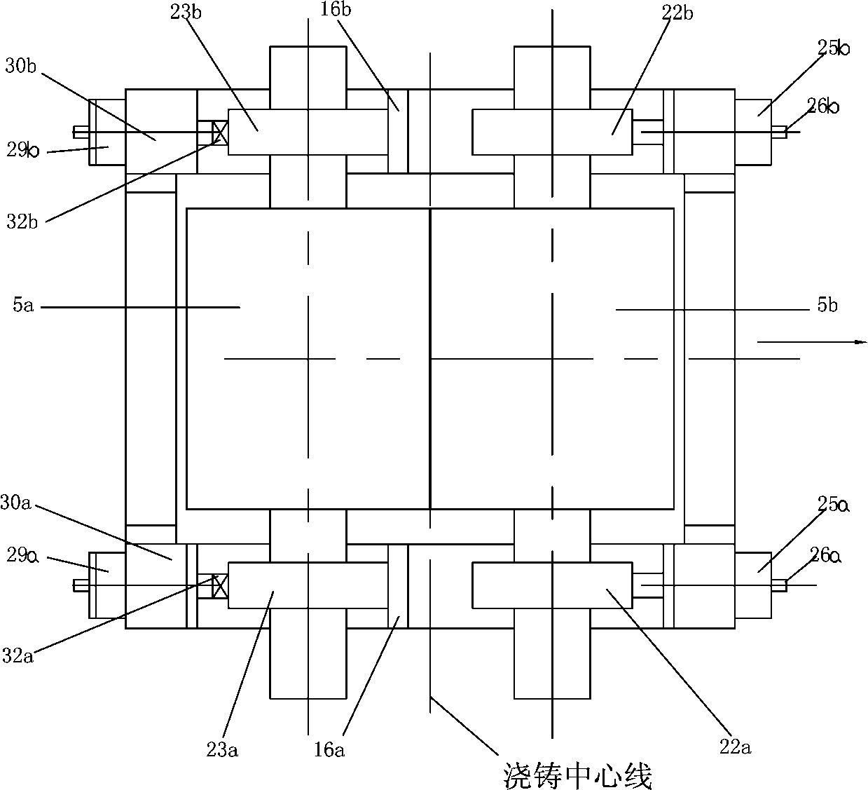
[0045] The frame archway 30 of the thin strip continuous casting machine is a U-shaped archway, and there are two archways, respectively supporting the bearing seats on both sides of each casting roll, and the casting roll bearing seats can drive the casting rolls on the frame archway 30 The guide rails slide freely, and the casting rolls can rotate freely under the support of rolling bearings in the bearing housings. Casting machine such as figure 2 The middle casting roll 5a is a fixed roll, while the casting roll 5b is defined as a moving roll, which can move back and forth relative to the ca...


PUM


Abstract

The invention discloses a method and a device for positioning a double-roller thin-strip continuous casting roller and adjusting a roller gap. A stand of a thin-strip continuous casting roller is a memorial arch with a U-shaped structure and is used for supporting bearing blocks on two sides of each casting roller; the bearing blocks can drive the casting roller to slide on a guide rail of the memorial arch; a hydraulic cylinder fixed on the U-shaped memorial arch of a casing machine can drive a movable roller to move relative to a fixed roller in a close or away manner; the size of a parallel gap, namely the size of the roller gap between the movable roller and the fixed roller is adjusted; a fixed stop block is arranged on one side, which corresponds to the bearing roller of the fixed roller and is close to a casting center line, on the stand; after the casting roller is replaced for each time, the casting center line of the casting machine is calibrated; the axis of the casting roller is adjusted to be parallel to the casting center line by adjusting the thickness of the fixed stop block on the stand; and meanwhile, the distance between two casting rollers is limited by the fixed stop block. According to the method and the device disclosed by the invention, the position of the fixed roller can be correspondingly adjusted along with the change of the diameter of the casting roller, so that the axis of the casting roller is parallel to the casting center line of the casting machine; and on the other hand, the detection precision of a casting and rolling force can be improved and the casting stability is improved.

Description

technical field [0001] The invention relates to continuous casting equipment, in particular to a method and device for positioning twin-roll strip continuous casting rolls and adjusting roll gaps. Background technique [0002] A typical example of twin roll strip casting is figure 1 As shown, the molten steel in the ladle 1 is poured directly through the nozzle 2, the tundish 3 and the flow distributor 4 in a room surrounded by two relatively rotating casting rolls 5a, 5b capable of rapid cooling and side sealing devices 6a, 6b. In the molten pool 7 of the casting roll, the molten steel solidifies on the circumferential surface of the casting roll, and then forms a solidified shell and gradually grows, and then forms a 1-5 mm thick metal thin strip 11 at the smallest gap (nip point) between the two casting rolls. In the airtight chamber 10, guided by the guide plate 9, the pinch roll 12 is sent to the rolling mill 13 to be rolled into a thin strip of 0.7-2.5mm, then cooled ...

Claims


Application Information

Patent Timeline
Patent Type & Authority Applications(China)
IPC IPC(8): B22D11/06
Inventor 叶长宏方园郑群杜锋韩月生
Owner BAOSHAN IRON & STEEL CO LTD
Why Eureka
Try Eureka