Imprinting equipment

A technology of equipment and transmission disc, applied in the field of engraving equipment, can solve the problems of low production efficiency, small transmission chain pitch, complex structure, etc., and achieve the effect of improving engraving efficiency, wide and solid structure

Inactive Publication Date: 2013-07-03
LISHUI FORGEWANG TOOL MFG
View PDF7 Cites 17 Cited by
  • Summary
  • Abstract
  • Description
  • Claims
  • Application Information

AI Technical Summary

Problems solved by technology

The current common conveyor belts are soft in texture and the pitch of the transmission chain is small. When punching hard workpieces, these transmission mechanisms cannot directly withstand the impact force of up to 10 tons
Therefore, the stamping device of the prior art also needs a feeding mechanism to place the workpieces sent by the conveyor belt or the transmission chain to a stable station before punching. Therefore, the structure is complicated, the process steps are many, and the production efficiency is high. lower

Method used


Image

  • Imprinting equipment
  • Imprinting equipment
  • Imprinting equipment

Examples


Embodiment Construction

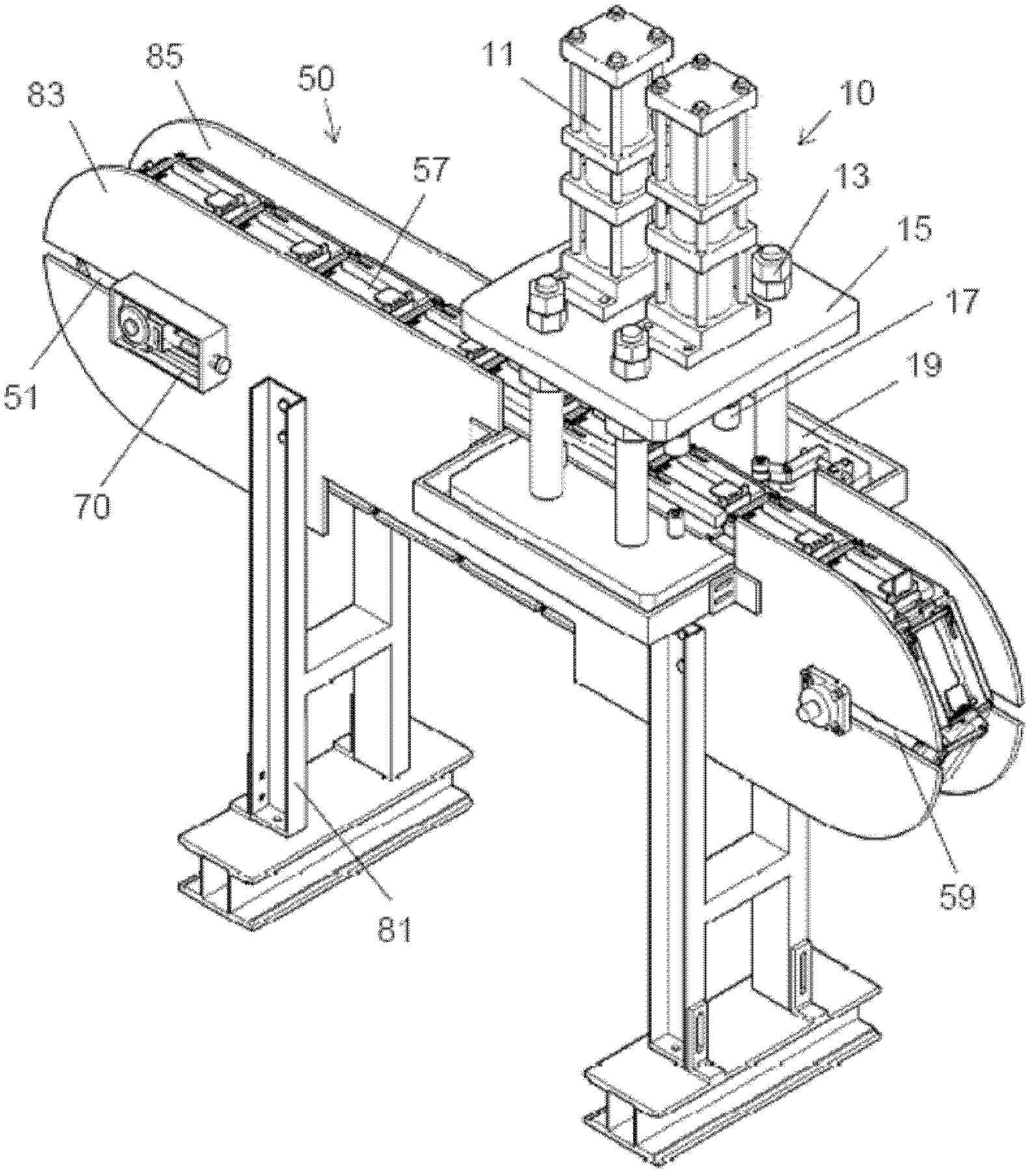
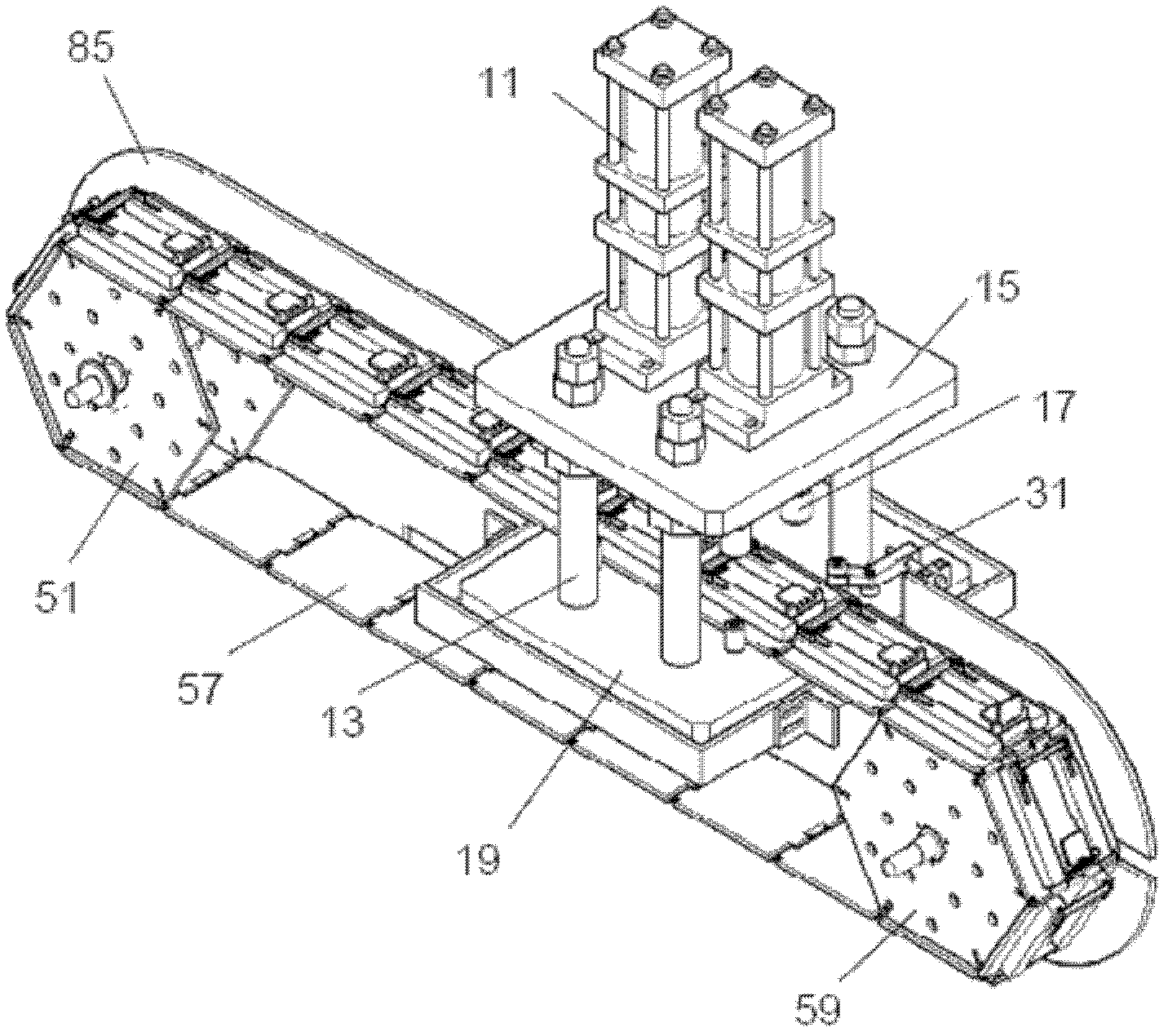
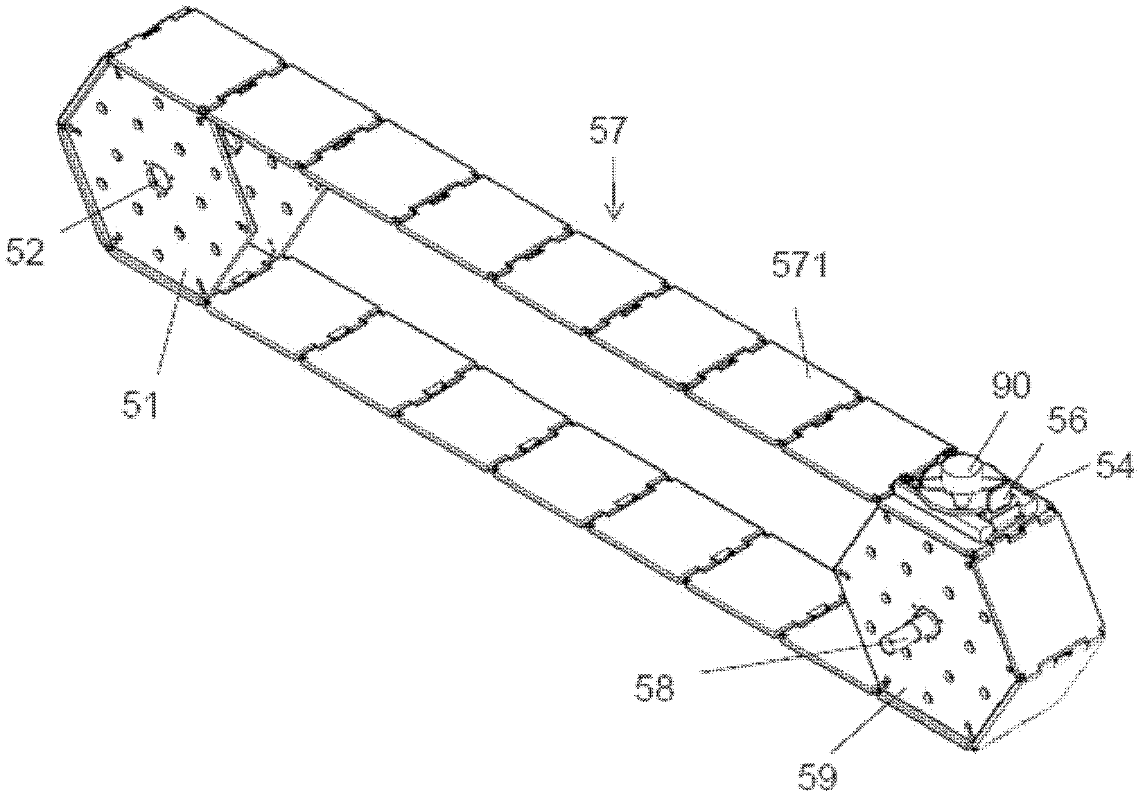
[0024] Such as figure 1 , Figure 5 As shown, a preferred embodiment of the present invention is a device for marking by stamping, which is mainly composed of a stamping mechanism 10 , a transmission mechanism 50 and a control system 30 . Transfer mechanism 50 will be engraved workpiece 90 (referring to image 3 ) is transferred to the station where the punching mechanism 10 is located, and punching can be directly carried out without going through another feeding mechanism. The control system 30 controls the synchronization of the stamping mechanism 10 and the transfer mechanism 50 through the computer 32 . The stamping mechanism 10 and the transmission mechanism 50 are installed on a frame composed of a bracket 81 , a first baffle 83 and a second baffle 85 .

[0025] Such as figure 1 , figure 2 As shown, the stamping mechanism 10 includes two cylinders 11, an upper template 15 and a lower template 19 connected by four pillars 13, and two groups of punch assemblies 17 r...


PUM


Abstract

The invention discloses imprinting equipment. Imprinting is realized in a stamping mode. The imprinting equipment comprises a punch engraving mechanism and a conveying mechanism, wherein the punch engraving mechanism comprises two cylinders, an upper template, a lower template and two groups of punch head components; the upper template and the lower template are connected through a plurality of supporting columns; the two groups of punch head components are pushed by the two cylinders respectively; the two cylinders are arranged on the upper template and penetrate through the upper template to push the punch head components to move up and down; each group of punch head components comprises two punch heads; and the punch heads are provided with character dies or forming dies to imprint characters or patterns on a workpiece to be imprinted. According to the imprinting equipment, four marks can be imprinted by all the four punch heads at most at one time, and the imprinting of two workpieces can be simultaneously finished by each process beat at an imprinting station; and if only one mark is required by each workpiece, four workpieces can be processed at one time, so that the imprinting efficiency is greatly increased. The link plate structure of the imprinting equipment is wide and strong and is sufficient to directly bear the impact force reaching up to 10 tons applied by the two cylinders through the four punch heads.

Description

technical field [0001] The invention relates to a marking device, which is used for marking characters and patterns on metal parts. Background technique [0002] In order to carry out quality control, many industries, such as the automobile industry, require that various parts and components are engraved with identification information such as batch numbers and article numbers for subsequent quality tracking. The current common marking methods include pre-engraving text or patterns in the mold, so that the injection molded or cast parts are formed with the required information, or marking the finished parts manually or mechanically, or using chemical etching , laser or plasma ablation and other methods for marking. [0003] Manual marking is inefficient, chemical etching will cause pollution, and it is also a problem for the protection of the surface of metal parts. Laser or plasma equipment is expensive, and the marking speed of burning is not high. It is relatively econo...

Claims


Application Information

Patent Timeline
Patent Type & Authority Applications(China)
IPC IPC(8): B41K3/04
Inventor 蓝伟林
Owner LISHUI FORGEWANG TOOL MFG
Why Eureka
Try Eureka