Pneumatic magnetic pump

A magnetic pump and pump body technology, which is applied in the direction of pumps, pump devices, non-variable pumps, etc., can solve the problems of large liquid flow pulse and large shear rate, and achieve small pulse, avoid impact and corrosion, and low noise Effect

Inactive Publication Date: 2013-07-03
BEIJING UNIV OF TECH
View PDF6 Cites 5 Cited by
  • Summary
  • Abstract
  • Description
  • Claims
  • Application Information

AI Technical Summary

Problems solved by technology

[0003] In order to overcome the defects of large liquid flow pulse and high shear rate in the application of the existing pneumatic diaphragm pump, the present invention provides a magnetic driven and pneumatic pneumatic magnetic pump to replace the existing pneumatic diaphragm pump

Method used


Image

  • Pneumatic magnetic pump
  • Pneumatic magnetic pump
  • Pneumatic magnetic pump

Examples


Embodiment Construction

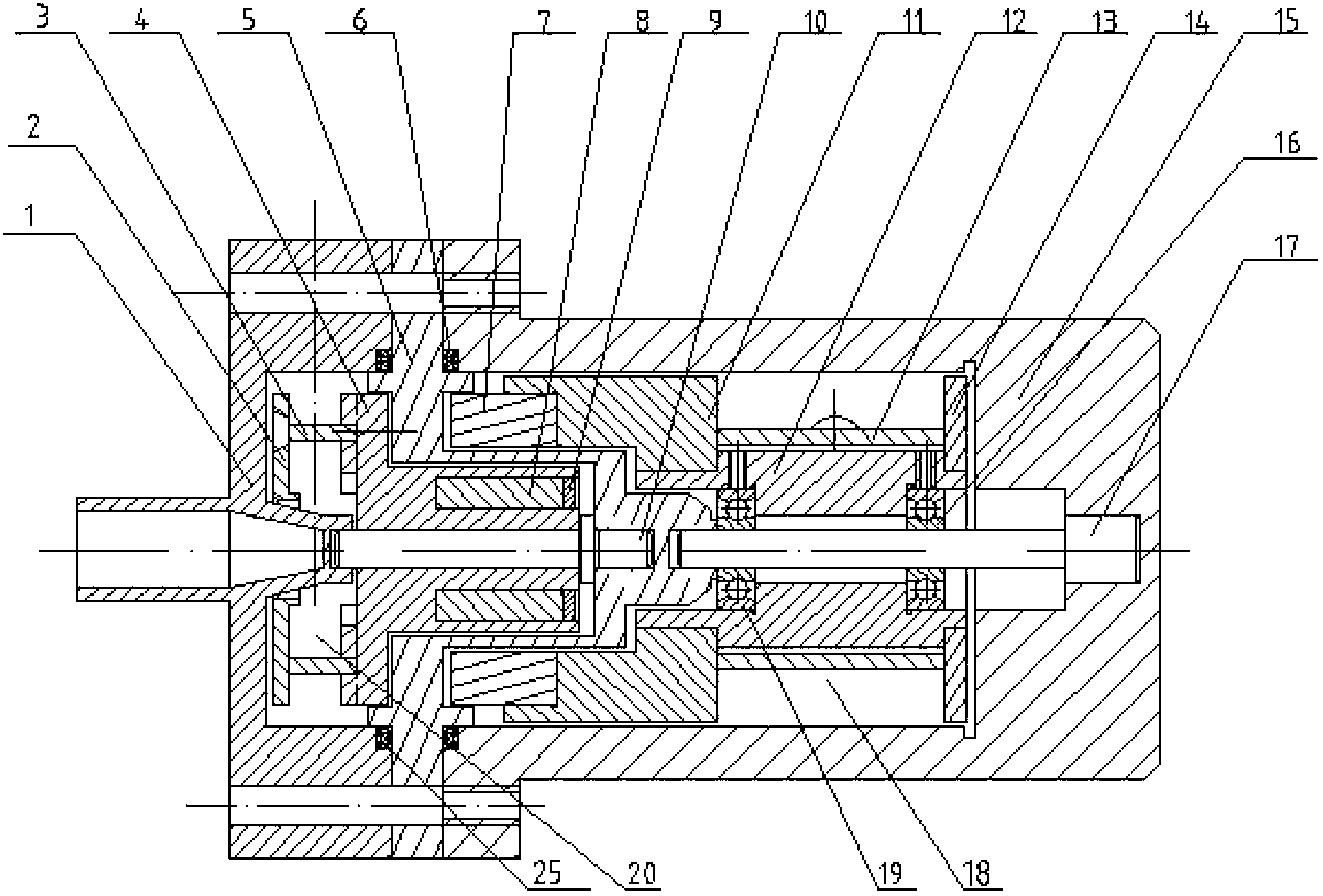
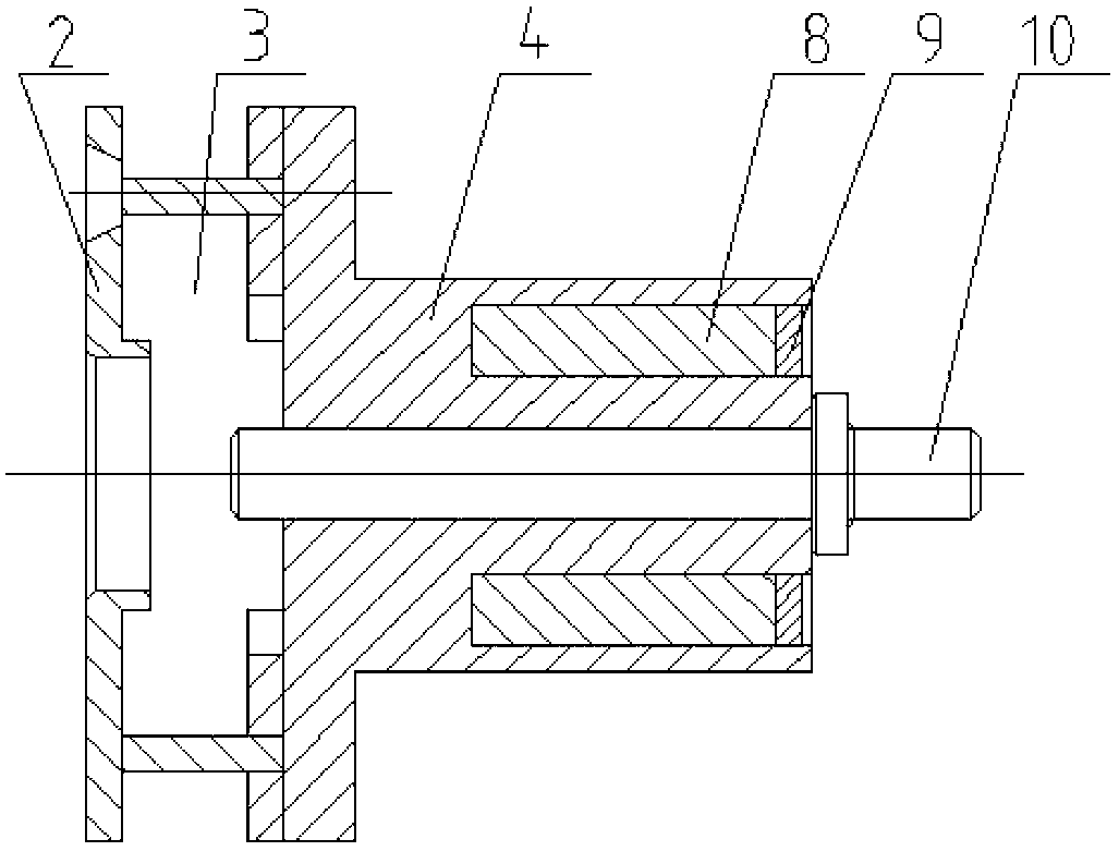
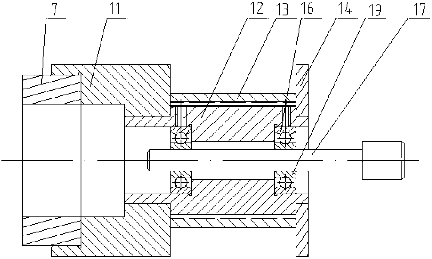
[0028] Such as Figure 1 to Figure 11 As shown, a pneumatic magnetic pump device includes a left pump body 1, a conveying part 20, a conveying impeller shaft 10, a sealing ring 6, a shielding sleeve 5, a driving part 18, a driving impeller shaft 17, a deep groove ball bearing I16, a deep groove Ball bearing II19, right pump body 15;

[0029] The left pump body 1, conveying part 20, conveying impeller shaft 10, shielding sleeve 5, driving part 18, driving impeller shaft 17, and right pump body 15 are connected in sequence; the conveying impeller shaft 10 is located between the left pump body 1 and the shielding sleeve 5 Between them, the conveying part 20 is set on the conveying impeller shaft 10; the conveying impeller shaft 10 is connected with the shielding sleeve 5 in the way of interference fit and shaft shoulder positioning, and adopts a clearance fit with the conveying part 20 and the left pump body 1; the driving impeller The wheel shaft 17 is located between the shiel...


PUM


Abstract

The invention discloses a pneumatic magnetic pump and belongs to the technical field of magnetic driving and pneumatics. A conveying impeller shaft is positioned between a left pump body and a shielding sleeve; a conveying component is sleeved on the conveying impeller shaft; a driving impeller shaft is positioned between the shielding sleeve and a right pump body and is connected with a driving component through a deep groove ball bearing; the driving component is formed by sequentially connecting an outer magnetic ring, a driving impeller left baffle, a driving impeller framework, a driving vane and a driving impeller right baffle; the conveying component is formed by sequentially connecting a conveying impeller left baffle, a conveying vane, a conveying impeller framework, an inner magnetic ring and a conveying impeller right baffle; and the left pump body, the shielding sleeve and the right pump body are connected through bolts, and are sealed by O-shaped rubber sealing rings, with high tightness. The pneumatic magnetic pump has superior performance to a pneumatic diaphragm pump, has the significant advantages of no leakage, continuous and uniform liquid conveying, energy conservation, environment friendliness, safety, reliability, convenience for use and the like, and is wide in application.

Description

technical field [0001] The invention belongs to the field of magnetic drive and pneumatic technology, and specifically relates to a new type of pneumatic magnetic pump, which can replace the widely used pneumatic diaphragm pump in some aspects, and has the advantages of no leakage, continuous and uniform liquid delivery, energy saving, environmental protection, safety and reliability, and convenient use. And other outstanding advantages, can be widely used in painting, ceramics, environmental protection, wastewater treatment, construction, sewage, coal mines, fine chemicals and other industries. Background technique [0002] With the continuous improvement of production, life and technological level, the continuous expansion of application scope and the continuous increase of the complexity of working conditions, users have higher and higher requirements for pump performance. The design of the pump has changed from the simplest structural types to a wide variety of structure...

Claims


Application Information

Patent Timeline
Patent Type & Authority Applications(China)
IPC IPC(8): F04D13/02
Inventor 王新华蔡娇艳高燕龚志奔郑刚孙树文
Owner BEIJING UNIV OF TECH
Why Eureka
Try Eureka