A micro-structure light guide plate and an edge type backlight module

A backlight module and microstructure technology, applied in optics, light guides, light sources, etc., can solve the problems of high printing point brightness, increase the cost of backlight modules, and high ink costs, and achieve improved production yield, good light guide effect, The effect of increasing productivity

Inactive Publication Date: 2014-12-24
CHI MEI CORP
View PDF4 Cites 2 Cited by
  • Summary
  • Abstract
  • Description
  • Claims
  • Application Information

AI Technical Summary

Problems solved by technology

[0003] However, due to the relatively high brightness of the printed dots of this type of printed light guide plate 1, it is generally necessary to use a diffuser film to atomize and conceal blemishes, and use a prism sheet to collect light to meet its optical and appearance requirements, resulting in an increase in the cost of the backlight module. cost; and this type of printed light guide plate 1 has the disadvantages that the uniformity of the printed structure 12 is not easy to control and the viscosity of the printing ink is not easy to control.
Moreover, the cost of the ink is high, if the amount of printing ink cannot be reduced, the manufacturing cost of the light guide plate 1 will be relatively high
In addition, because the inner surface 11 of the light guide plate 1 is a planar design, it will produce obvious scratches once it is scratched. Therefore, it is known that after the light guide plate 1 is manufactured, an additional protective film must be used to cover the inner surface 11 for protection.
[0004] Another type of light guide plate is a microstructured light guide plate, which is provided with a special shape microstructure on the light emitting surface of the light guide plate, such as a triangular prism lens, a curved lenticular lens, etc. The above microstructure design The purpose is to break the total reflection condition and let the light out, but this kind of microstructured light guide plate is used in the backlight module, although the use of prism sheets can be saved, but because the inner surface of the light guide plate is a flat design, once it is scratched, it will be damaged. If there are obvious scratches, a protective film must also be used to cover the inner surface to protect the

Method used


Image

  • A micro-structure light guide plate and an edge type backlight module
  • A micro-structure light guide plate and an edge type backlight module
  • A micro-structure light guide plate and an edge type backlight module

Examples


Embodiment Construction

[0039] The present invention will be described in detail below with reference to the accompanying drawings and embodiments. It should be noted that in the following description, similar elements are denoted by the same numerals.

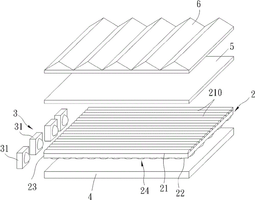
[0040] refer to figure 2 , 3 , the first preferred embodiment of the edge-lit backlight module of the present invention includes: a microstructured light guide plate 2 , a light source 3 , a reflection plate 4 , a diffusion film 5 , and a prism sheet 6 .

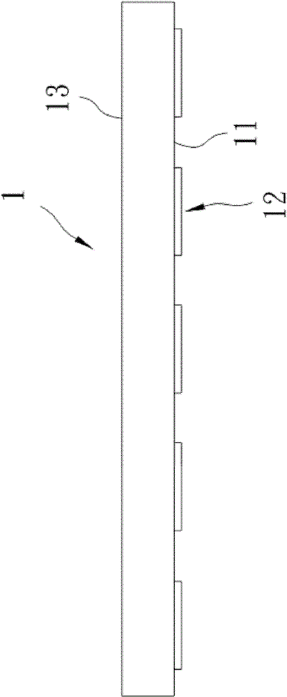
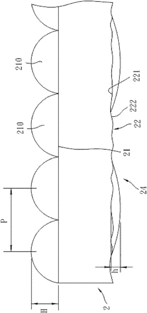
[0041] The microstructured light guide plate 2 includes: a light-emitting surface 21, a rough inner surface 22 located on the opposite side of the light-emitting surface 21, a light-incident surface 23 connected to one side of the light-emitting surface 21 and the inner surface 22, and a light-incident surface 23 located on the inner surface 22. 24 on the printed structure. Wherein, the light-emitting surface 21 has a plurality of columnar microstructures 210 extending in the longitudinal direct...


PUM


Abstract

A micro-structure light guide plate and an edge type backlight module, the micro-structure light guide plate comprises: a smooth surface, an inner surface with a roughness surface opposite to the smooth surface, and a light incident surface connecting the smooth surface to one side of the inner surface. The height H of the micro-structure of the smooth surface is 60-150[mu]m, a micro-structure pitch is P, and H / P is 0.25 to 0.5. The inner surface includes a first area having a printing structure on the surface, and a second area not having a printing structure on the surface. Through the roughened inner surface cooperating with appropriate area distributed printing structures, the light guide plate is enabled to have a good reflection effect, and the amount of printing ink is reduced, costs are lowered, and the roughened inner surface may make scratches on the plate looks not obvious with the effect of covering defects, eliminating the use of protective film.

Description

technical field [0001] The invention relates to a light guide plate and a backlight module, in particular to a light guide plate with a microstructure on the surface and a side-light backlight module. Background technique [0002] refer to figure 1 , is a known light guide plate (Light Guide Plate) 1, which plays a key light guiding medium in the backlight module, and is applied to the edge type (Edge Type) backlight module, which can guide the light direction, Improve the brightness of the panel and control the uniformity of brightness. Currently, the light guide plate 1 used for the backlight of a liquid crystal display device (LCD) is a printed light guide plate, that is, the printing material containing highly divergent light substances is properly distributed on the inner surface 11 of the light guide plate 1 to form an array printing. The structure 12, through the properties of the printing material to absorb and diffuse light, destroys the internal propagation cause...

Claims


Application Information

Patent Timeline
Patent Type & Authority Patents(China)
IPC IPC(8): G02B6/00F21S8/00F21V8/00F21V19/00F21Y101/02F21Y115/10
Inventor 陈信宏郭俊良林正丰
Owner CHI MEI CORP
Why Eureka
Try Eureka