Pull box assembly for replacing battery and method for replacing the battery

A battery replacement and pull-out box technology, which is applied to battery components, electrical components, circuits, etc., can solve the problems of increasing labor intensity and burden of staff, cumbersome battery replacement steps, and unfavorable time saving, etc., and achieves simple structure, Easy installation and disassembly, simple and convenient operation steps

Active Publication Date: 2013-07-03
BEIJING AEONMED
View PDF5 Cites 11 Cited by
  • Summary
  • Abstract
  • Description
  • Claims
  • Application Information

AI Technical Summary

Problems solved by technology

However, the power of the battery is limited, and it is often encountered that the voltage is too low or the power is insufficient, and it needs to be replaced
Existing machines (especially large-scale equipment) have many structural compone

Method used


Image

  • Pull box assembly for replacing battery and method for replacing the battery
  • Pull box assembly for replacing battery and method for replacing the battery
  • Pull box assembly for replacing battery and method for replacing the battery

Examples


Example

[0076] First embodiment

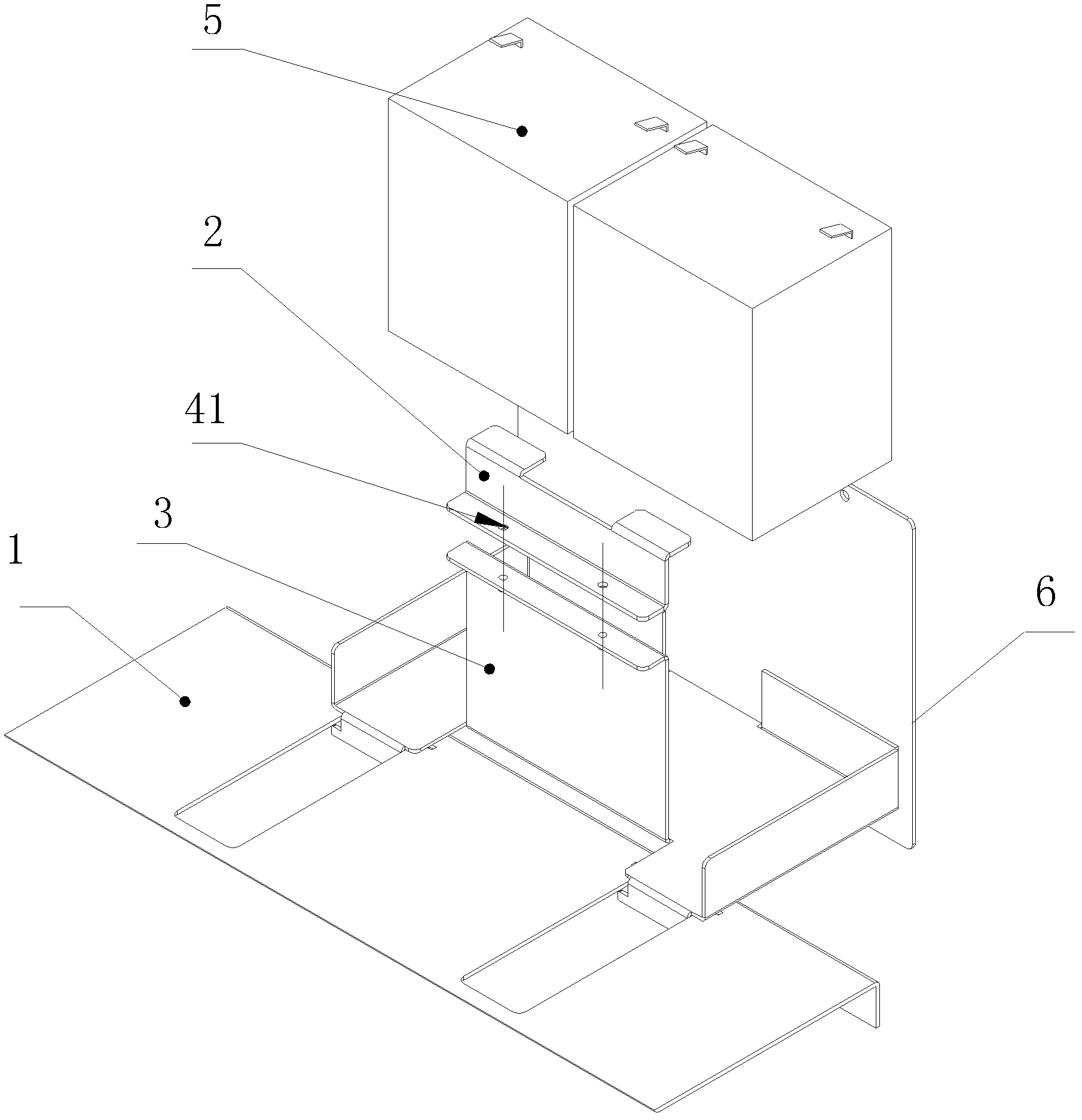
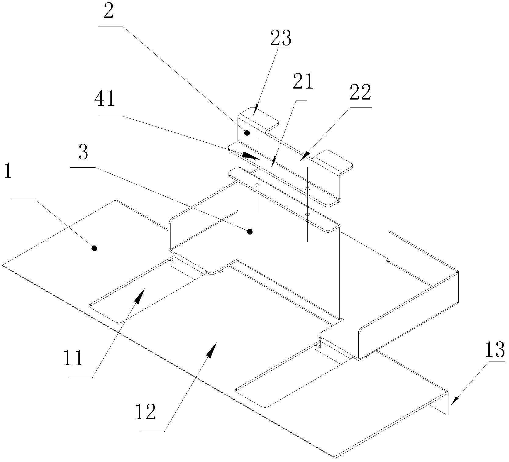
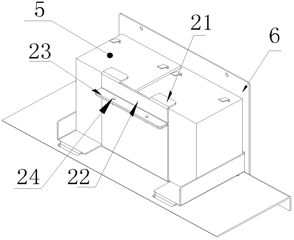
[0077] The technical solution in this embodiment provides a battery installation structural assembly, which includes a battery drawer box 3, a drawer box fixing plate 1, a battery fixing plate 2, a rear cover plate 6, and the battery drawer box is suitable for Install two batteries 5.

[0078] Wherein, the battery drawing box 3 is provided with a sliding structure 31, a drawing limiting structure 32, a battery limiting structure 33, and a drawing handle 34; wherein the battery limiting mechanism 33 includes a first side limiting surface 33-1 , The second side limiting surface 33-2, the third side limiting surface 33-3, the fourth side limiting surface 33-4, and the bottom limiting surface 33-5.

[0079] The drawer box fixing plate 1 is provided with a bottom support plate 12 and a side fixing plate 13, which are folded at right angles. At least one chute structure 11 is provided on the bottom support plate 12, and a side fixing plate 13 is provided There i...

Example

[0096] Second embodiment

[0097] See Figure 2-3 This embodiment provides a method for replacing the battery according to the battery mounting assembly in the first embodiment.

[0098] The initial installation method of the installation component includes the following steps:

[0099] Step A: The battery drawer box 3 is inserted into the sliding groove structure 11 of the drawer box fixing plate 1 through the sliding structure 31, so that it can be pushed and pulled back and forth; the draw limit structure 32 of the battery drawer box 3 can control the battery draw The drawer 3 cannot be detached from the drawer fixing plate 1. This step A enables the battery drawer 3 to slide along the sliding groove structure 11 of the drawer fixing plate 1 from the initial zero displacement position to the maximum displacement pulling limit position;

[0100] Step B: Use the pull handle 34 to pull the battery pull box 3 to the pull limit position of the maximum displacement;

[0101] Step C: Pla...

Example

[0116] The third embodiment

[0117] Such as Picture 9 As shown, the technical solution in this embodiment provides a battery mounting structure assembly, which includes a battery drawer box 103, a drawer box fixing plate 101, and a battery fixing plate 102, which are suitable for installation in the battery drawer box. At least one battery 105.

[0118] Wherein, the battery drawing box 103 is provided with a sliding structure 131, a drawing limiting structure 132, a battery limiting structure 133, and a drawing handle 134; wherein the battery limiting mechanism 133 includes a first side limiting surface 133-1 , The second side limiting surface 133-2, the third side limiting surface 133-3, the fourth side limiting surface 133-4, and the bottom limiting surface 133-5. The battery drawer 103 has a battery limiting structure 133. The limiting structure 33 may be, for example, a bottom limiting surface and four side limiting surfaces. The bottom limiting surface 133-5 limits the down...


PUM


Abstract

The invention provides a pull box assembly for replacing a battery, comprising a battery pull box, a pull box fixing plate and a battery fixing plate, wherein the battery pull box has a sliding structure, a pull spacing structure, a battery spacing structure and a pull handle; the pull box fixing plate has a chute structure and a battery pull box fixing hole; the battery fixing plate has a battery fixing hole; the sliding structure of the battery pull box is matched to the chute structure of the pull box fixing plate, and the battery pull box is prevented by the pull spacing structure of the battery pull box from being released from the pull box fixing plate; and the battery spacing structure of the battery pull box and the battery fixing hole of the battery fixing plate together restrict the displacement of the battery in the forward-back, left-right and up-down six directions. The pull box assembly has advantages of simple structure and simple battery replacing steps, and greatly raises convenience in a battery replacing process.

Description

technical field [0001] The present invention relates to a drawer box assembly, more specifically, to a drawer box assembly of a battery that can be easily disassembled and replaced, and a method for using the drawer box assembly to replace a battery. Background technique [0002] Most of the existing machines require power supply, but when the external power supply is not available, it is inconvenient to supply power, or a power supply obstacle occurs, a built-in battery device is required for energy supply. In particular, the role of the battery is very important in order to avoid damage to the ongoing work caused by sudden power failures or even failures. However, the power of the battery is limited, and it is often encountered that the voltage is too low or the power is insufficient, and needs to be replaced. Existing machines (especially large-scale equipment) have many structural components for battery installation, and the battery replacement steps are cumbersome, whi...

Claims


Application Information

Patent Timeline
IPC IPC(8): H01M2/10
CPCY02E60/10
Inventor 陈庚
Owner BEIJING AEONMED
Why Eureka
Try Eureka