
Centrifugal aluminum casting die for shaftless rotor of motor

A centrifugal casting and shaftless technology, which is applied in the manufacture of stator/rotor body, etc., can solve the problems of non-conforming appearance of shaftless rotors, fragile ventilation hole covers, waste of ventilation hole covers, etc., and achieves low cost and excellent structure Simplicity, high production efficiency and practical efficiency

Inactive Publication Date: 2013-07-10
SHANDONG HUALI ELECTRIC MOTOR GRP
View PDF0 Cites 8 Cited by
  • Summary
  • Abstract
  • Description
  • Claims
  • Application Information

AI Technical Summary

Problems solved by technology

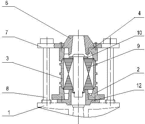
However, we can see that the upper mold 4 and the sprue bushing 6, the lower inner mold 12 and the lower mold 2, the ventilation hole cover plate 10 and the cast aluminum shaft are superimposed in a two-body structure. In the production, or in use, it will bring some troubles to the operator
When the upper mold 4 and the sprue sleeve 6, the lower inner mold 12 and the lower mold 2 are manufactured, the taper is easy to be mismatched. In use, the upper mold 4 and the sprue sleeve 6, the lower inner mold 12 and the lower mold There will be aluminum clamping, and the appearance of the shaftless rotor produced in this way does not meet the requirements. The ventilation hole cover plate 10 and the cast aluminum shaft are two-body structure. When the aluminum shaft is cast back, the ventilation hole cover plate 10 is easily broken. Shaft rotor, a waste of a ventilation hole cover, resulting in a significant increase in motor costs

Method used


Image

  • Centrifugal aluminum casting die for shaftless rotor of motor
  • Centrifugal aluminum casting die for shaftless rotor of motor

Examples


Embodiment Construction

[0010] The present invention will be further described below in conjunction with the accompanying drawings and embodiments.

[0011] figure 1 It is a structural cross-sectional view of a centrifugal casting aluminum mold for a shaftless rotor of a motor in the prior art. The structure of the aluminum casting mold has been described in detail in the background technology section, and will not be repeated here.

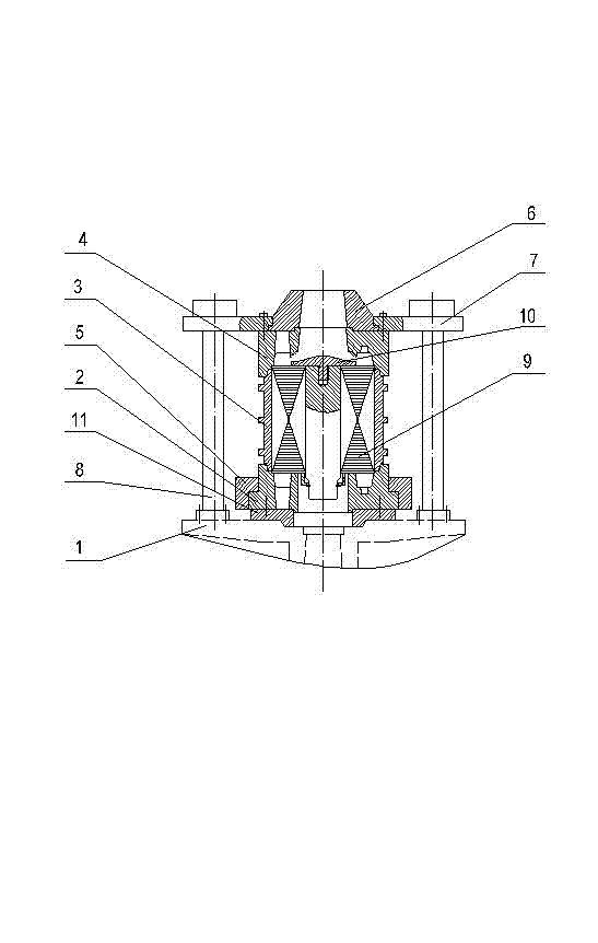
[0012] figure 2 It is a structural schematic diagram of the present invention, such as figure 2 As shown, in this embodiment, the motor shaftless rotor centrifugal casting aluminum mold includes the lower mold 2 on the turntable 1, the middle mold 3 on the lower mold 2 and the upper mold 4 on the middle mold 3, and the lower mold 2 Pressed by the lower mold base 5, the lower mold 2 and the middle mold 3, and the middle mold 3 and the upper mold 4 are connected by joints respectively, and the upper mold 4 is equipped with a gate sleeve 6, and the upper mold 4 and the...


PUM


Abstract

The invention relates to a die, and aims to solve the technical problem in a conventional die for centrifugally casting aluminium to a shaftless rotor of a motor. The practical scheme is that a centrifugal aluminium casting die for a shaftless rotor of a motor is provided, and comprises a low die, a lower die bearing plate, a middle die and an upper die, wherein the lower die and the lower die bearing plate are arranged on a turntable; the middle die is arranged on the lower die; the upper die is arranged on the middle die; a sprue bushing is mounted on the upper die; a rotor core is mounted in the middle die; and a ventilation hole cover plate is mounted at the top of an aluminum casting shaft of the rotor core. The centrifugal aluminum casting die is characterized in that the lower die and the lower die bearing plate are matched and connected through a spigot; the upper die and the sprue bushing are matched and connected through a spigot; and the ventilation hole cover plate at the top of the aluminum casting shaft is in threaded connection with the aluminum casting shaft. The centrifugal aluminum casting die has a simple structure, is low in cost, reasonable in process, and higher in production efficiency and practical efficiency, ensures the aluminum cannot enter into the ventilation hole, improves the shaftless rotor quality, and reduces the production cost.

Description

[0001] technical field [0002] The invention relates to a mold, in particular to a centrifugal casting aluminum mold for a shaftless rotor of a motor. Background technique [0003] In the motor industry, it is the most economical to use centrifugal cast aluminum for shaftless rotors, so it is widely used in manufacturers. Traditional centrifugal casting aluminum mold assembly such as figure 1 As shown, the mold includes an upper mold 4, a middle mold 3, a lower mold 2 and a lower inner mold 12, the lower inner mold 12 is fixed on the turntable 1, the lower mold 2 sits on the lower inner mold 12, and the middle mold 3 sits on the lower mold 2 Above, the upper mold 4 is installed on the middle mold 3, and the sprue sleeve 6 is installed on the upper mold 4. The upper mold 4 and the sprue sleeve 6 are pressed by the upper mold base 7, and the upper mold base 7 and the turntable 1 are connected by a tie rod. 8 tighten, install the rotor core 9 inside the middle mold 3, and in...

Claims


Application Information

Patent Timeline
IPC IPC(8): B22D13/10H02K15/02
Inventor 吕桂梅毕华东王炳龙
Owner SHANDONG HUALI ELECTRIC MOTOR GRP
Learn More