
Connecting device for beam main shaft mounting board of PCB digital control drilling machine

A technology of CNC drilling machine and connecting device, which is applied in drilling/drilling equipment, metal processing machinery parts, parts of boring machine/drilling machine, etc. , insufficient screw rigidity, etc., to achieve the effect of improving the accuracy and stability of the whole machine, reducing deformation, and preventing degeneration

Inactive Publication Date: 2013-07-10
SUZHOU NINGLIN PHOTOELECTRIC SCI & TECHCO
View PDF2 Cites 2 Cited by
  • Summary
  • Abstract
  • Description
  • Claims
  • Application Information

AI Technical Summary

Problems solved by technology

The disadvantage of this connection method is: each spindle mounting plate is only partially connected and constrained, and the rigidity of the screw is not enough, resulting in insufficient rigidity of the spindle mounting plate movement and poor stability; when the X-axis in the bed direction is moving at high speed , each axis will twist, deform and oscillate in the directions of front and back, up and down, etc., causing the drilling spindle perpendicular to the beam to vibrate violently, and the drilling accuracy of the spindle will naturally deteriorate

Method used


Image

  • Connecting device for beam main shaft mounting board of PCB digital control drilling machine
  • Connecting device for beam main shaft mounting board of PCB digital control drilling machine

Examples


Embodiment Construction

[0020] The preferred embodiments of the present invention will be described in detail below in conjunction with the accompanying drawings, so that the advantages and features of the present invention can be more easily understood by those skilled in the art, so as to define the protection scope of the present invention more clearly.

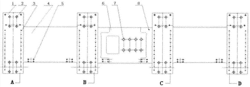
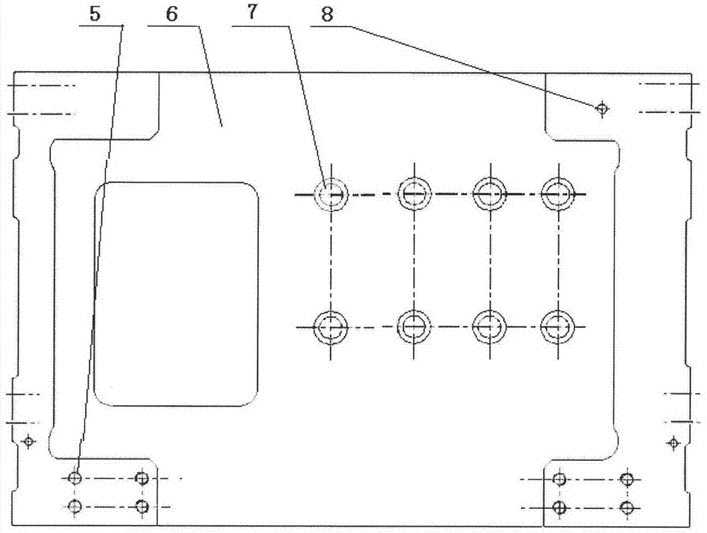
[0021] Such as Figure 1 to Figure 2 A circuit board CNC drilling machine crossbeam spindle mounting plate connection device shown includes a linear guide rail device, a side mounting plate 4, a spindle mounting plate device, and an intermediate mounting plate device; the linear guide rail device is fixed by a linear guide rail and a guide rail Bolts and guide rail sliders are composed, and the linear guide rails are installed as required; the spindle mounting plate device is composed of a beam guide rail slider, a spindle mounting plate 1, and a spindle guide rail. The spindle mounting plate 1 is fixed to the beam guide rail slider, and the spind...


PUM


Abstract

The invention provides a connecting device for a beam spindle mounting board of a PCB (Printed Circuit Board) digital control drilling machine. The connecting device comprises a linear guide rail device, side mounting boards, main shaft mounting board devices and a center mounting board device, wherein the linear guide rail device composes a guide rail, guide rail fixing nuts and a guide rail sliding block; after the linear guide rail is mounted as per the requirement, the position of the sliding block can be adjusted; each main shaft mounting board device comprises a beam guide rail sliding block, a main shaft mounting board and a main shaft guide rail; each main shaft mounting board is fixed with the beam guide sliding block; and the main shaft guide rail is mounted on the main shaft mounting board, is well adjusted in precision and fixed on the main shaft mounting board through nuts. The connecting device is easy to mount and adjust, excellently solves the problem that the main shaft mounting boards of shaft I and shaft IV deform during mounting, and increases the drilling and machining accuracies of the whole machine.

Description

technical field [0001] The invention relates to the technical field of production of a circuit board numerically controlled drilling machine, in particular to a connection device for a main shaft mounting plate of a circuit board numerically controlled drilling machine. Background technique [0002] The precision of the circuit board CNC drilling machine is very important to the quality of the produced circuit board, but there are many factors that affect the precision of the drilling machine. The rigidity of each axis on the beam is particularly important to the accuracy. At present, in order to increase the speed of the circuit board CNC drilling machine, the weight of the moving part of the beam should be reduced as much as possible between the axes of the beam. Many brands of machines use simple screws for connection. , making the structure very simple. But at the same time, it also brings some adverse effects: the rigidity of the moving part of the beam is not enough, ...

Claims


Application Information

Patent Timeline
Patent Type & Authority Applications(China)
IPC IPC(8): B23Q1/01B23B47/00
Inventor 周金梅
Owner SUZHOU NINGLIN PHOTOELECTRIC SCI & TECHCO
Learn More