High-precision laminating machine

A laminating machine, high-precision technology, applied in the direction of lamination device, lamination auxiliary operation, lamination, etc., can solve the problems of pressing thickness deviation, height limitation, difficult to quickly process parts with different thicknesses, etc., to achieve The effect of large rotational freedom, easy positioning and quick adaptation

Inactive Publication Date: 2013-07-10
WENSHAN KETAIFENG ELECTRONICS CO LTD
View PDF3 Cites 26 Cited by
  • Summary
  • Abstract
  • Description
  • Claims
  • Application Information

AI Technical Summary

Problems solved by technology

But present this type of gluing machine generally has problems and defects, such as, at first, for the convenience of loading and tearing off the protective film, the upper platform is often set to a flipping type, and this flipping processing will press down the upper and lower platforms and The rotation posture of the upper platform is integrated into a flipping action, so it is difficult to quickly process parts with different thicknesses. Moreover, when encountering parts with the same specification, the deviation in the pressing thickness cannot be adjusted in time; secondly, the laminating machine adopts two platforms To fix the two parts used for bonding, it is necessary to position the relative positions of the two, so that the horizontal position of the parts to be bonded is accurate. The height of the common laminating machine is limited when it is turned, and it is very inconvenient to position the parts to be processed.

Method used


Image

  • High-precision laminating machine
  • High-precision laminating machine
  • High-precision laminating machine

Examples


Embodiment Construction

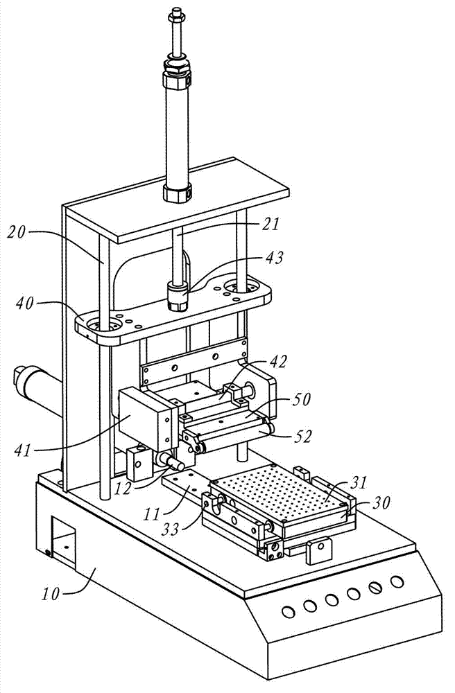
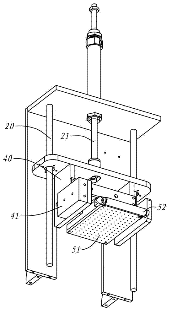
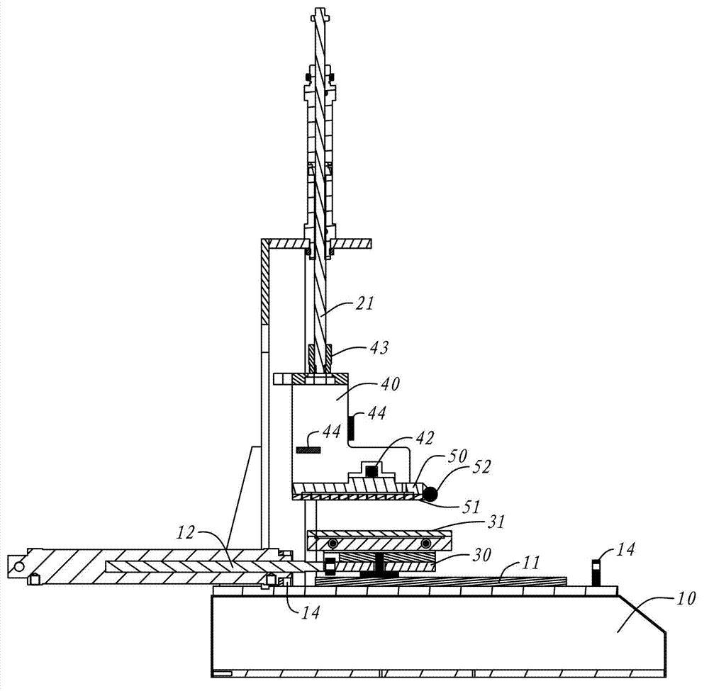
[0029] Such as Figure 1 to Figure 4 Shown is a schematic diagram of an embodiment of the present invention.

[0030] In this embodiment, a high-precision laminating machine is a device placed on a horizontal workbench. It includes a base 10 and a vertical rail 20 vertically fixed above the base 10. Wherein, the upper surface of the base 10 is provided with a horizontal rail 11, the horizontal rail 11 is arranged in a horizontal and linear shape, the horizontal rail 11 is movably matched with a platform 30, that is, the lower platform 30 can slide one-dimensionally along its direction on the horizontal rail ; The lower platform 30 is a carrying component, the top of which has a lower bonding surface 31, this lower bonding surface 31 is used for vacuum adsorption of the parts to be bonded.

[0031] The vertical rail 20 becomes the restraining mechanism for the upper part of the base 10. A sliding frame 40 is slidably fitted to the vertical rail 20, that is, the sliding frame 40 ca...


PUM


Abstract

The invention discloses a high-precision laminating machine which is characterized by comprising a base and a vertical rail, wherein a transverse rail is arranged on the base, a lower platform is movably cooperated with the transverse rail, the top of the lower platform is provided with a lower laminating surface, the vertical rail is vertically fixed above the base, a sliding support is upward and downward slidingly cooperated with the vertical rail, an upper platform is rotatably cooperated with a transverse shaft of the sliding support, and the lower end of the upper platform is provided with an upper laminating surface. The sliding support is positioned at a high place of the vertical rail, and a to-be-laminated part is vac-sorbed on the upper laminating surface; then another to-be-laminated part is vac-sorbed on the lower laminating surface; the upper platform is rotated around a transverse axis thereof until the upper laminating surface is parallel to the lower laminating surface, then the sliding support falls along the vertical rail and applies a pressure until the two to-be-laminated parts are tightly bonded together through optical cement carried by the two parts, and therefore, a laminated product is obtained. According to a scheme in the invention, when the upper platform presses downwardly, the upper platform has uniform pressure relative to the lower platform, the downward pressing stroke of the upper platform is individually controlled by the sliding support, so high precision is obtained, and the laminating machine can rapidly adapt to laminated products with different thicknesses.

Description

Technical field [0001] The invention relates to a device for solid glue bonding of two light-transmitting parts of a display screen. Background technique [0002] The main structure of the existing display screens often includes light-transmitting multilayer forms, especially the display screens with touch function. In addition to the display function, they also have touch sensors covering the entire viewable area. These multilayer forms include protective shells. , ITO film, etc., need to use solid optical glue to fix each other. Taking into account the requirements of the display, the bonding surface where the optical adhesive is located must not have bubbles and need to be aligned horizontally. In this way, the laminating process is often realized by laminating machines. [0003] At present, a more common type of laminating machine, after the parts are vertically pressed together with the optical glue between the parts, a certain pressure is applied to the top of the parts to ...

Claims


Application Information

Patent Timeline
Patent Type & Authority Applications(China)
IPC IPC(8): B32B37/12B32B37/10B32B38/00
Inventor 张金祖邱锦辉
Owner WENSHAN KETAIFENG ELECTRONICS CO LTD
Why Eureka
Try Eureka