Coastal wave cyclone power generation method and installation

A power generation device and coastal wave technology, which is applied in the directions of ocean energy power generation, engine components, machines/engines, etc., can solve the problems of difficulty in capturing wave energy and uneconomical economy, and achieve good continuity and stability. The effect of improving the ecological environment

Inactive Publication Date: 2013-07-10
CHINA INST OF WATER RESOURCES & HYDROPOWER RES
View PDF12 Cites 13 Cited by
  • Summary
  • Abstract
  • Description
  • Claims
  • Application Information

AI Technical Summary

Problems solved by technology

There are relatively few studies on waves with an average wave power of less than 10KW / m, and there are relatively few designed facilities. The reason is that wave energy with an average wave power of less than 10KW / m is difficult to capture and economically uneconomical.
But if the waves of thousands of kilometers of coastline are within the range of 10KW / m, the energy contained in it is also amazing

Method used


Image

  • Coastal wave cyclone power generation method and installation
  • Coastal wave cyclone power generation method and installation
  • Coastal wave cyclone power generation method and installation

Examples


Embodiment 1

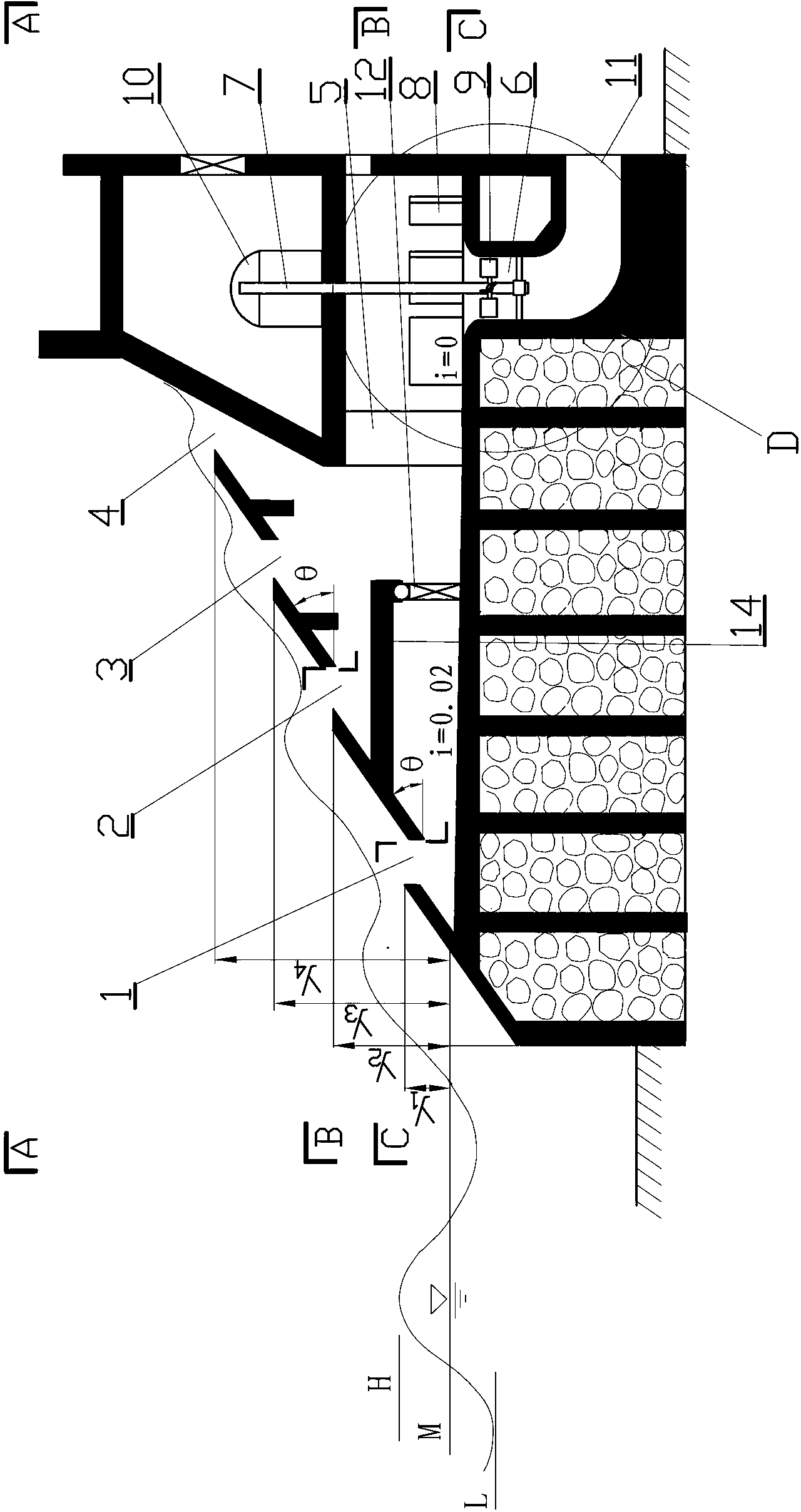
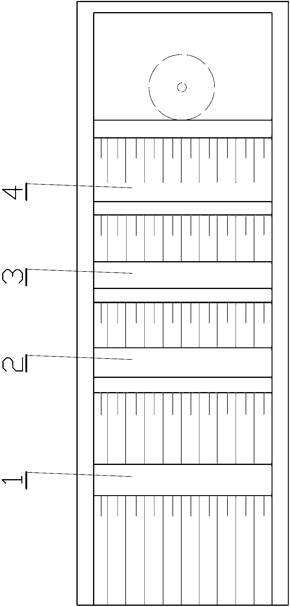
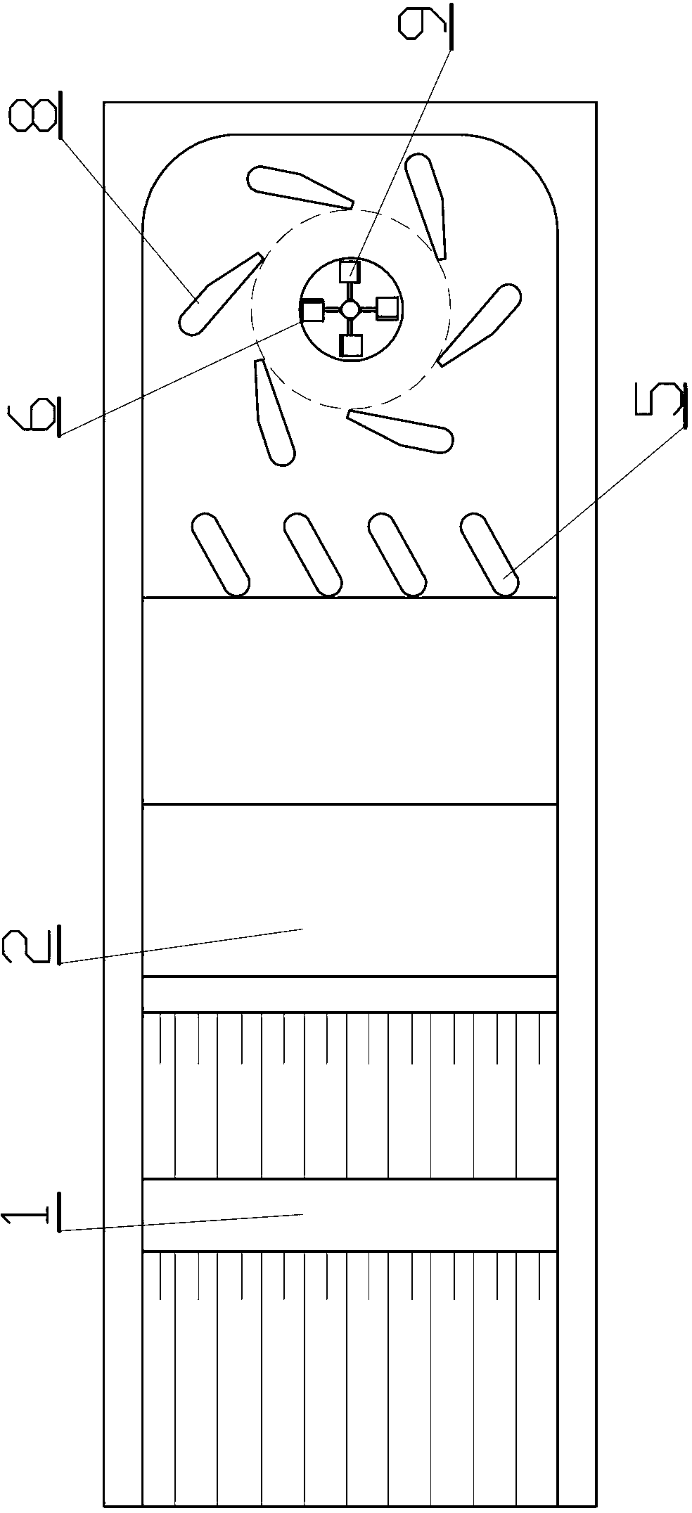
[0027] This embodiment is a coastal wave energy swirling power generation device, such as figure 1 , 2 , 3, 4, and 5. This embodiment includes: a slope facing the sea arranged on the coastline, and on the slope facing the sea, multi-layer water intakes ( Figure 1-4 Only 4 water intakes are drawn in the figure, which may actually be more than two water intakes), the water intakes are connected to the pools that store seawater, and the bottom plate of the pools is slightly lower than the average tide level. On the bottom plate of the pools A contraction diversion wall is set, and a one-way flap door is installed at the shrinkage port of the shrinkage diversion wall, and a plurality of diversion piers are arranged horizontally downstream of the one-way flap door, and a bell mouth vertical pipe is arranged downstream of the diversion piers , the bell-mouth standpipe is installed with a water turbine coaxially connected with the generator, and the bell-mouth standpipe is connect...

Embodiment 2

[0035] This embodiment is an improvement of the first embodiment, and it is a refinement of the first embodiment on the slope of the seaward surface. The oblique wave on the seaward surface described in this embodiment gradually widens from top to bottom, and energy-gathering side walls 15 (suitable for construction on distant sea islands) are arranged on both sides of the oblique wave on the seaward surface, as shown in Image 6 shown.

[0036] The energy-gathering side walls are two gradually retracted walls built on both sides of the slope facing the sea, which can make the width of the waves gradually narrow when they rush from the sea to the shore, and at the same time gradually increase the height of the waves, that is, the kinetic energy of the waves is Potential energy is formed between the two gradually gathering energy walls, which can rush into a higher water intake. Image 6 A slope facing the sea with four water intakes is drawn in , and if built on a coastline b...

Embodiment 3

[0038] This embodiment is an improvement of the above embodiment, and is a refinement of the above embodiment regarding the slope of the seaward surface. The inclination angle of the ramp wave on the seaward surface described in this embodiment is 30-35 degrees.

[0039] The slope between the water intakes of each layer can be changed, for example, the slope gradually increases from bottom to top, so that the width of the water intake can be increased.


PUM


Abstract

The invention relates to coastal wave cyclone power generation method and installation. The installation comprises a seaward slope on a coastline. Multiple tiers of water intakes for capturing sea wave and higher than mean tide level are arranged on the seaward slope. The lowermost first tier of water intakes is connected with a pool for accumulating sweater. An expansion guide wall is disposed on the bed of the pool. A one-way flap valve is mounted at an expansion opening of the expansion guide wall. A plurality of guide piers are transversely arranged on the downstream of the one-way flap valve. Flared vertical tubes are arranged on the downstream of the guide piers. Water turbines coaxially connected with a generator are installed in the flared vertical tubes. The flared vertical tubes are connected with draft tubes. Water flow generates venting vortexes by the aid of the flared vertical tubes and spiral piers at outer edges of flared openings, and the vortexes can drive the water turbines to rotate to generate power at various tide levels and low water heads. A foundation for the installation can be made of coarse aggregate concrete caissons and reinforced concrete superstructure and is built with a breakwater, engineering investment can be shared, and the cost of the power generation installation is lowered.

Description

technical field [0001] The invention relates to a coastal wave energy swirl power generation method and device, which is a wave power generation method and device, and a low water head shaft swirl power generation method and device. Background technique [0002] The existing shore-based wave power generation facilities are mostly used on coastlines with large waves, and the average wave power exceeds 20KW / m. There are relatively few studies on waves with an average wave power of less than 10KW / m, and there are relatively few designed facilities. The reason is that wave energy with an average wave power of less than 10KW / m is difficult to capture and economically uneconomical. But if the waves of thousands of kilometers of coastline are within the range of 10KW / m, the energy contained in it is also amazing. How to effectively utilize these weaker waves at low cost is a problem that should be solved. Contents of the invention [0003] In order to overcome the problems of t...

Claims


Application Information

Patent Timeline
IPC IPC(8): F03B13/22
CPCY02E10/30
Inventor 董兴林杨开林付辉郭新蕾郭永鑫王涛李甲振
Owner CHINA INST OF WATER RESOURCES & HYDROPOWER RES
Why Eureka
Try Eureka