Light emitting diode (LED) candle lamp

A technology of LED candle lamps and LED substrates, applied to lampshades, lighting devices, light sources, etc., can solve problems such as poor heat dissipation, easy failure, and repeated labor, and achieve improved stability and heat dissipation performance, and the bending angle can be adjusted The effect of adjusting and reducing workload

Inactive Publication Date: 2013-07-10
广东金达照明科技股份有限公司
View PDF8 Cites 3 Cited by
  • Summary
  • Abstract
  • Description
  • Claims
  • Application Information

AI Technical Summary

Problems solved by technology

[0003] However, this method has the following problems: (1) When assembling the LED lamp, it is necessary to install each LED substrate on the heat conduction column separately, which involves a lot of repetitive work and low assembly efficiency; (2) It is necessary to give each LED Punching holes in the base board and setting up the connecting wires are complicated and error-prone; (3) Since each LED base board independently leads the connecting wires to the power module for power supply, the internal wiring of the LED lamp is complicated and prone to failure, which is not conducive to Maintenance; (4) Many parts and high cost
[0004] For this reason, a three-dimensional LED substrate has been proposed in the industry. Since the aluminum substrate in the LED substrate is rigid and difficult to bend, special equipment is required to bend the aluminum substrate, and the aluminum substrate needs to be processed for different lamps. different angles, which not only makes the processing more troublesome, but also the bending angle of the aluminum base layer cannot be adjusted after processing. Therefore, due to processing errors and other factors, it is often difficult for the three-dimensional LED substrate to fit the heat conduction column perfectly, so the LED substrate will be fixed. Firm, poor heat dissipation and other issues

Method used


Image

  • Light emitting diode (LED) candle lamp
  • Light emitting diode (LED) candle lamp

Examples


Embodiment Construction

[0021] The present application is further described in conjunction with the following examples.

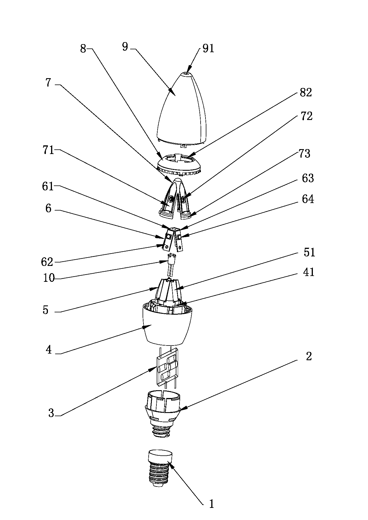
[0022] A specific embodiment of an LED candle lamp in the present application, such as figure 1 and figure 2 As shown, it includes: a base, a power supply assembly 3 is arranged inside the base, a radiator 4 is connected to one end of the base, and a heat conduction column 5 is fixedly arranged on the other end of the radiator 4, and the heat conduction column 5 is covered with A three-dimensional LED module substrate 6 formed by bending a flat plate is provided. The LED module substrate 6 includes a regular power connection area 61 and no less than two LED substrate areas connected to the power connection area 61 62, the connection between the power supply connection area 61 and the LED substrate area 62 is provided with a bendable crease area 63, and the power supply connection area 61 and the LED substrate area 62 sequentially include an aluminum base layer, an insulating lay...


PUM


Abstract

The invention relates to the technical field of a light emitting diode (LED) lamp, and in particular relates to an LED candle lamp. An LED module substrate of the LED candle lamp is provided with a crease area, the crease area is not provided with an aluminum substrate and only comprises a flexible insulation layer and a flexible circuit layer which has bending properties, an angle between an LED substrate area and a power connection area can be flexibly adjusted by bending the crease area, a planar LED module substrate can be changed to a three-dimensional module substrate which can be perfectly bonded with a heat conduction column; and when in assembling, the heat conduction column can be directly nested in the three-dimensional module substrate to be fixed. Compared with the prior art, the LED module substrate is simple to assemble and can be installed in place in one step after being bent; and moreover, the bending angle is adjustable, the LED module substrate can be effectively perfectly bonded with the heat conduction column, and the firmness and the heat radiation performance of the LED module substrate after being fixed can be improved.

Description

technical field [0001] The present application relates to the technical field of LED lamps, in particular to an LED candle lamp. Background technique [0002] LED candle lamp refers to the lamp whose light source is LED lamp and whose shape is similar to that of a candle flame. The structure of this lamp requires that the LED candle lamp must have a 360° luminous angle to achieve better lighting effects, and the luminous angle of the LED lamp is limited. Therefore, LED candle lamps are generally equipped with a heat conduction column and a plurality of LED lights are arranged around the side of the heat conduction column, so that the lamp can emit light at 360°. In the existing LED lamps, in order to obtain a 360° lighting angle, many lamps, such as candle lamps, generally adopt a heat conduction column, and set a plurality of LED substrates around the side of the heat conduction column, and at the same time set LED lights on the LED substrate, so that It enables the lamp t...

Claims


Application Information

Patent Timeline
Patent Type & Authority Applications(China)
IPC IPC(8): F21S2/00F21V23/00F21V3/00F21Y101/02F21K9/23F21Y115/10
Inventor 庾健航
Owner 广东金达照明科技股份有限公司
Why Eureka
Try Eureka