Five-freedom active magnetic bearing type dual-axis angular rate gyroscope

A technology of active magnetic bearings and rate gyroscopes, applied in rotating gyroscopes and other directions, can solve the problems of poor gyroscope bandwidth and sensitivity adjustment ability, low gyroscope anti-overload ability, and large gyroscope drift rate, etc., to achieve small gyroscope drift rate and convenient gyroscope Bandwidth and sensitivity, the effect of solving disturbance torque

Active Publication Date: 2013-07-10
BEIHANG UNIV
View PDF5 Cites 33 Cited by
  • Summary
  • Abstract
  • Description
  • Claims
  • Application Information

AI Technical Summary

Problems solved by technology

The high-speed rotor of the patent ZL201110287382.7 "High-precision hemispherical dynamic pressure motor dynamic tuning gyroscope" adopts opposed hemispherical dynamic pressure bearings, and utilizes the characteristics of gas lubrication, so that the vibration amplitude generated by the dynamic pressure bearings is 1- 2 orders of magnitude, but the support problem has not been fundamentally solved, and there is a problem of large gyro drift rate; the patent ZL200810017908.8 "a magnetic levitation gyroscope" uses a magnetic field to float the gyro float, which reduces the interference torque, but the structure is complicated. The anti-overload ability of the gyro is low; the patent 200610028646.6 "electrostatic support suspension electromagnetic induction rotating micro gyro" overcomes the limitation of the electromagnetic damping on the speed, the heat generation is small, and the support rigidity is high, but because the electrostatic support adopts open-loop control, the bandwidth and sensitivity of the gyro can be adjusted poor ability

Method used


Image

  • Five-freedom active magnetic bearing type dual-axis angular rate gyroscope
  • Five-freedom active magnetic bearing type dual-axis angular rate gyroscope
  • Five-freedom active magnetic bearing type dual-axis angular rate gyroscope

Examples


Embodiment Construction

[0017] The present invention will be further described in detail below in conjunction with the accompanying drawings and implementation examples.

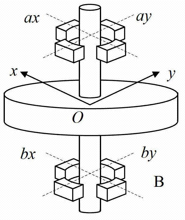
[0018] The present invention uses the electromagnetic torque of the radial magnetic bearing to offset the gyro torque of the high-speed magnetic levitation rotor. Because the electromagnetic torque is equal to the gyro torque in the steady state, the external input angular rate and the electromagnetic torque are in a linear relationship, and the current torque is driven by the coil current Generated, the magnitude of the external input angular rate can be calculated by detecting the driving current of the coil.

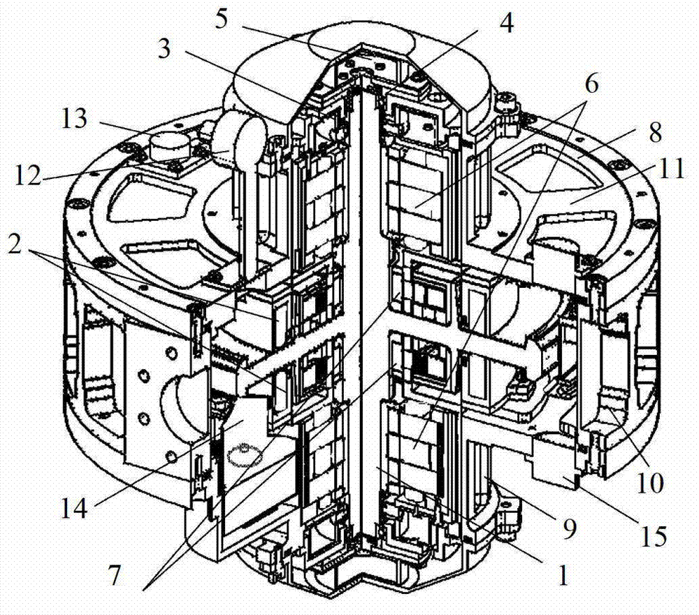
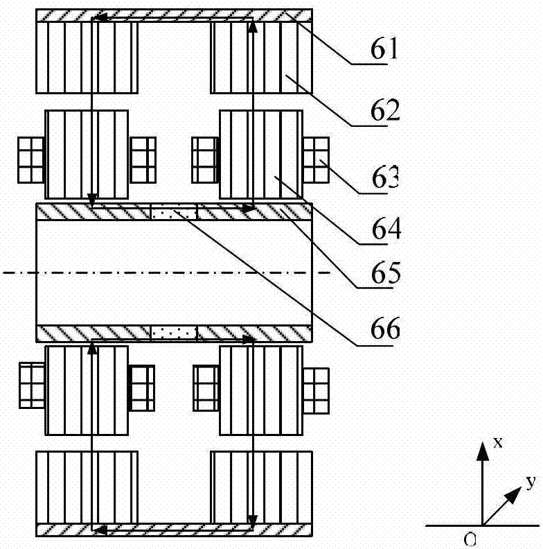
[0019] Such as figure 1 As shown, the driving motors 7 implemented in the present invention need to be used in pairs and be located in the middle of the rotor 1, the axial magnetic bearings 2 need to be used in pairs and be located outside the driving motor 7, and the radial magnetic bearings 6 need to be used in pairs and...


PUM


Abstract

The invention discloses a five-freedom active magnetic bearing type dual-axis angular rate gyroscope. The five-freedom active magnetic bearing type dual-axis angular rate gyroscope consists of rotors, a radial magnetic bearing, an axial magnetic bearing, a protection bearing, a radial displacement sensor, an axial displacement sensor, a driving motor, gyroscope cases and a circuit system. By using position feedback information of the rotors of the radial sensor and the axial sensor relative to the gyroscope cases, the circuit system regulates the coil winding current of the radial magnetic bearing and the axial magnetic bearing in real time, so that the five-freedom fully-active suspension of the rotors is realized, and the rotors are driven by the driving motor to rotate at a high speed so as to generate an angular momentum. When the attitude of an external rotor is changed, the coil winding current is correspondingly changed, and the magnitude of external input angular rate is calculated according to a linear relationship between the coil winding current and the input angular rate. The five-freedom active magnetic bearing type dual-axis angular rate gyroscope is applicable to the field of high-accuracy angular rate measurement application, and has the characteristics of small zero offset, low output noise, high resolution and the like.

Description

technical field [0001] The invention relates to an angular rate gyroscope, in particular to a five-degree-of-freedom active magnetic bearing type dual-axis angular rate gyroscope. Background technique [0002] Gyroscope is a widely used inertial device, which has been widely used in aviation, aerospace, navigation, and some civilian fields. As one of the most important inertial instruments, the angular rate gyroscope directly determines the accuracy of the inertial navigation and guidance system. With the development of science and technology, the requirements for gyro performance are getting higher and higher. High precision, high reliability, miniaturization, multi-axis measurement and multi-function measurement have become the development requirements of future inertial sensors. [0003] The support mode of the gyro high-speed rotor and the frame torque device are two key factors affecting the gyro precision. The high-speed rotor of the patent ZL201110287382.7 "High-pre...

Claims


Application Information

Patent Timeline
Patent Type & Authority Applications(China)
IPC IPC(8): G01C19/02G01C19/24
Inventor 郑世强韩邦成孙津济刘刚房建成
Owner BEIHANG UNIV
Why Eureka
Try Eureka