High-productivity thin film deposition device and thin film batch production method

A thin film deposition device, high-yield technology, applied in the direction of ion implantation plating, metal material coating process, coating, etc., can solve the problems of increasing vacuuming time and vacuuming amount, reducing production efficiency, increasing costs, etc., to achieve improved Product quality, overall production capacity improvement, and the effect of production capacity improvement

Pending Publication Date: 2018-06-12
SUZHOU NEW MATERIAL INST
View PDF0 Cites 0 Cited by
  • Summary
  • Abstract
  • Description
  • Claims
  • Application Information

AI Technical Summary

Problems solved by technology

Therefore, the current equipment and technology not only increase the vacuuming time and amount of vacuuming, increase energy consumption, but also reduce production efficiency, increase the difficulty of product quality control, and greatly increase the cost

Method used


Image

  • High-productivity thin film deposition device and thin film batch production method
  • High-productivity thin film deposition device and thin film batch production method
  • High-productivity thin film deposition device and thin film batch production method

Examples


Embodiment 1

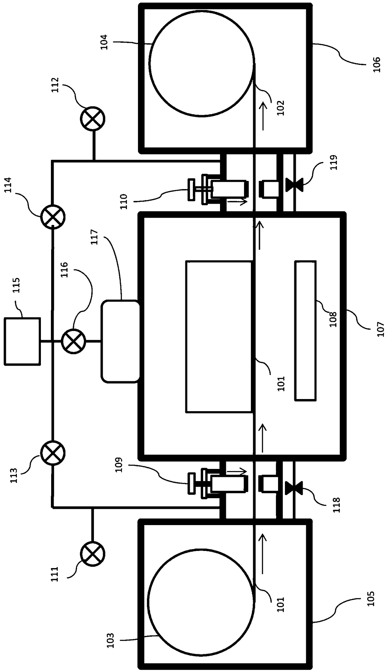
[0039] Such as figure 1 As shown, this embodiment relates to a high-yield thin film deposition device, including: a raw tape reel chamber 105, a product tape reel chamber 106, and at least one deposition chamber 107 with a deposition source 108;

[0040]The original base tape reel 103 and the product base tape reel 104 are arranged in the original tape reel chamber 105 and the product tape reel chamber 106, and the original base tape reel 103 and the product base tape reel 104 are connected to the tape transport system. In this example, a deposition chamber 107 is provided. In actual use, a plurality of deposition chambers can be set and one of the deposition chambers has a deposition source while the other deposition chambers do not have a deposition source. The original tape reel chamber 105 is connected to the deposition chamber 107 through the first base tape vacuum lock 109, and the deposition chamber 107 passes through a second base tape vacuum lock 110 is connected to t...

Embodiment 2

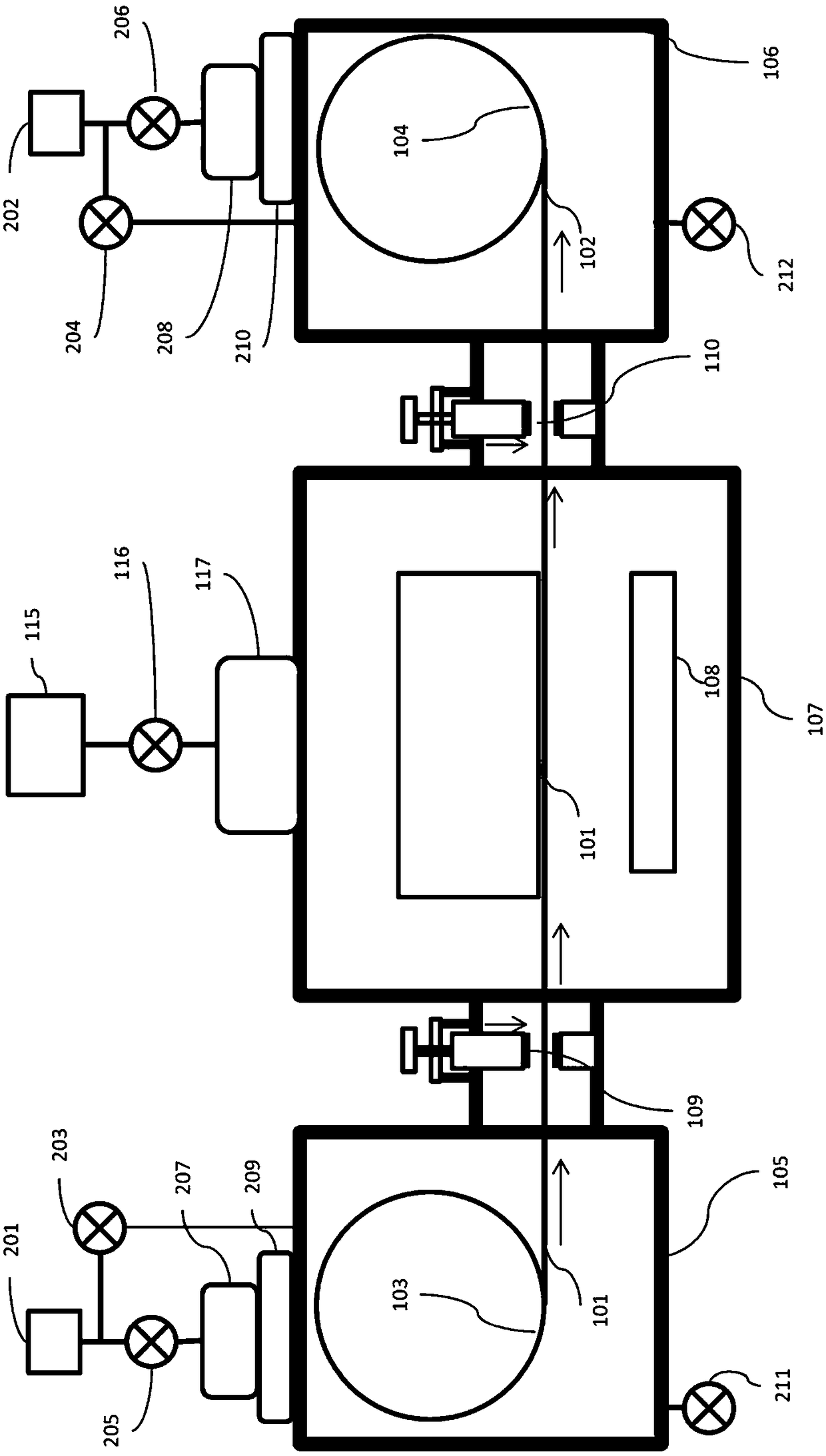
[0061] Such as figure 2 As shown, this embodiment relates to a high-capacity thin film deposition device. The difference from Embodiment 1 is that in Embodiment 2, the original tape reel chamber 105 and the product tape reel chamber 106 have independent vacuuming devices. There is no need to stop sputtering between depositions, minimizing the time between depositions, further increasing productivity.

[0062] Specifically, the original tape reel cavity 105 is connected to the second high vacuum pump 207 through the first high vacuum valve 209, and the second high vacuum pump 207 is connected to the second rough vacuum pump 201 through a pipeline. A first support valve 205 is provided between the vacuum pumps 201, a second rough vacuum pump 201 is connected to the original tape reel chamber 105 through a pipeline and a fourth rough valve 203 is arranged on the pipeline;

[0063] The product tape reel cavity 106 is connected to the third high vacuum pump 208 through the second...


PUM

PropertyMeasurementUnit
surface roughnessaaaaaaaaaa

Abstract

Disclosed are a high-productivity thin film deposition device and a thin film batch production method in the technical field of industrial coating. The high-productivity thin film deposition device comprises at least one deposition cavity, an original strip reel cavity and a product strip reel cavity. The deposition cavity is internally provided with a deposition source. An original base strip reel connected with a strip conveying system is arranged in the original strip reel cavity, and the original strip reel cavity is connected with the deposition cavity through a first base strip vacuum lock. A product base strip reel connected with the strip conveying system is arranged in the product strip reel cavity. The product strip reel cavity is connected with the deposition cavity through a second base strip vacuum lock. The original strip reel cavity, the deposition cavity and the product strip reel cavity are all connected with vacuumizing devices and vacuum removing devices. The first base strip vacuum lock and the second base strip vacuum lock conduct high-vacuum sealing on the original strip reel cavity, the deposition cavity and the product strip reel cavity under the circumstances that a strip penetrates through the first base strip vacuum lock and the second base strip vacuum lock and the strip is in a stationary state. According to the high-productivity thin film deposition device and the thin film batch production method, operation environments of unreeling, coating and reeling are separated, the time needed by work preparation of the high-productivity thin film deposition device before deposition is reduced, product quality and productivity are improved, and energy consumption and production cost are lowered.

Description

technical field [0001] The invention relates to a technology in the field of industrial coating, in particular to a high-capacity thin film deposition device and a batch production method for thin films. Background technique [0002] Ion sources are increasingly used in the thin film deposition industry because the use of ion sources can greatly improve product quality and performance. For example, the Low-E film, the silver film of the functional layer has poor environmental corrosion resistance, so it can only be sealed in double-layer glass; but there is an increasing demand for Low-E film on single-layer glass in the market In such products, the Low-E film is directly exposed to the external environment, which puts forward high requirements for its environmental corrosion resistance. In addition, the single-layer glass Low-E film directly faces various operations in production and use. , It also puts forward high requirements on the mechanical damage resistance of the f...

Claims


Application Information

Patent Timeline
Patent Type & Authority Applications(China)
IPC IPC(8): C23C14/56
CPCC23C14/562
Inventor 熊旭明王延凯陈慧娟蔡渊
Owner SUZHOU NEW MATERIAL INST
Why Eureka
Try Eureka