Anti-theft telescopic integral discharge current device
What is Al technical title?
Al technical title is built by PatSnap Al team. It summarizes the technical point description of the patent document.
A telescopic device and electric current technology, applied in the direction of track devices, conductors, circuits, etc., can solve the problems of copper bars that cannot be repaired and wasted, easy to enter concrete, and exposed, so as to ensure project quality and construction progress, convenient construction, and conductive strong effect
Inactive Publication Date: 2016-03-23
XUCHANG TIETONG MARK +1
View PDF5 Cites 0 Cited by
Summary
Abstract
Description
Claims
Application Information
AI Technical Summary
This helps you quickly interpret patents by identifying the three key elements:
Problems solved by technology
Method used
Benefits of technology
Problems solved by technology
[0002] At present, all kinds of transportation, railways, bridges, tracks, tunnel expansion joint stray current drainage terminals and stray current drainage strips (networks) are connected by welding the drainage strips and copper terminals or extruding welding terminals, punching holes, etc. , wires, connecting bolts, pads, wire clips, wires, easy to enter the concrete in the hole, many mechanical joints, exposed, easy to steal, oxidized, loose, the more joints, the greater the resistance, the long connecting conductor, and the copper bar cannot be used after being stolen. Repair waste labor, materials, money, complicated construction time, low work efficiency
Method used
Image
Click on the blue label to locate the original text in one second.
Reading with bidirectional positioning of images and text.
Examples
Embodiment Construction
[0015] Below in conjunction with accompanying drawing, the present invention will be further described:
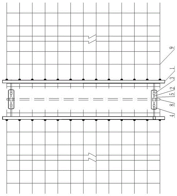
[0016] Such as figure 1 , figure 2 As shown in the figure, an anti-theft telescopic integral current discharge device includes a drainage strip 9 arranged in the ballast bed and a filling plate arranged in the expansion joint 8. It is characterized in that the drainage strip 9 is welded to the metal plate 1, A test terminal 7 is arranged on the metal plate 1, and the metal plate 1 is connected to the line 2 through the connection point 6, and a telescopic drainage device located on the expansion joint 8 is arranged between the lines 2;
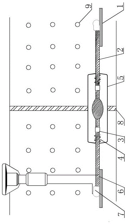
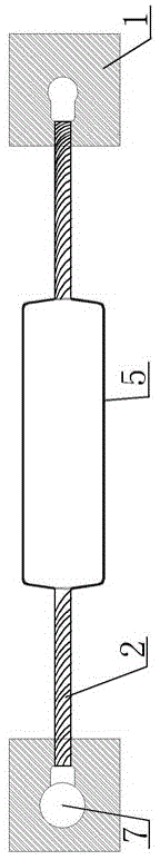
[0017] Such as image 3 , Figure 4 As shown, the telescopic drainage device includes a sealing cover 5, and a telescopic device 4 arranged in the sealing cover 5 and connected to the wire 2, the telescopic device 4 is connected to the first holder 3 and the second holder through the wire 2 ;
[0018] All the longitudinal steel bars ...
PUM
Abstract
The invention discloses an anti-theft expansion integral current drainage device which comprises a current drainage strip arranged in a ballast bed and an infilling board arranged in an expansion joint, wherein the current drainage strip is welded with a metal board, a testing terminal is arranged on the metal board which is connected with wires through connecting points, and an expansion current drainage device body which is located on the expansion joint is arranged between the wires. The expansion current drainage device body comprises a sealing cover and an expansion device which is arranged in the sealing cover and is connected with the wires. The expansion device is connected with a first fixer and a second fixer through the wires. According to the anti-theft expansion integral current drainage device, the metal board is copper-cladded or alumetized and connected with the wires, the integral connection can meet expansion quantity of the expansion joint, construction is convenient, easy and fast, mechanical splice does not exist, the whole device is buried by concrete and is not exposed, and the anti-theft expansion integral current drainage device is firm, free of loss, strong in electric conduction, low in resistance, anti-theft, not prone to abrasion, free of maintenance, long in service life, labor-saving, material-saving and cost-saving. The expansion integral current drainage device can effectively meet the expansion quantity of the expansion joint, and ensure project quality and construction schedule of a stray current drainage system.
Description
technical field [0001] The invention is applicable to stray current drainage systems for expansion joints of various types of traffic, railways, bridges, tracks, and tunnels, and is specifically an anti-theft telescopic integral current drainage device. Background technique [0002] At present, all kinds of transportation, railways, bridges, tracks, tunnel expansion joint stray current drainage terminals and stray current drainage strips (networks) are connected by welding the drainage strips and copper terminals or extruding welding terminals, punching holes, etc. , wires, connecting bolts, pads, wire clips, wires, easy to enter the concrete in the hole, many mechanical joints, exposed, easy to steal, oxidized, loose, the more joints, the greater the resistance, the long connecting conductor, and the copper bar cannot be used after being stolen. Repairing wastes manpower, material, money, complicated construction takes a long time, and work efficiency is low. Contents of ...
Claims
Application Information
Patent Timeline
Application Date:The date an application was filed.
Publication Date:The date a patent or application was officially published.
First Publication Date:The earliest publication date of a patent with the same application number.
Issue Date:Publication date of the patent grant document.
PCT Entry Date:The Entry date of PCT National Phase.
Estimated Expiry Date:The statutory expiry date of a patent right according to the Patent Law, and it is the longest term of protection that the patent right can achieve without the termination of the patent right due to other reasons(Term extension factor has been taken into account ).
Invalid Date:Actual expiry date is based on effective date or publication date of legal transaction data of invalid patent.