Integration circuit integrated structure

A circuit integration and circuit layer technology, applied in the direction of circuits, electrical components, electric solid devices, etc., can solve the problems of shortening the life of electronic components, narrow application range, low power supply efficiency, etc., to avoid inaccurate coverage positions and low cost , the effect of improving efficiency

Inactive Publication Date: 2013-07-10
余原生 +2
View PDF6 Cites 5 Cited by
  • Summary
  • Abstract
  • Description
  • Claims
  • Application Information

AI Technical Summary

Problems solved by technology

[0003] However, when the aluminum substrate is used, the withstand voltage cannot meet the safety certification requirements, so an isolated power supply must be used, resulting in low power supply efficiency and high cost; if a ceramic substrate is used, although the withstand voltage can meet the safety certification requirements, the cost is several times that of the aluminum substrate. times; while adding heat sinks and fans to the components to be dissipated is not only costly but also narrow in scope of application
[0004] In addition, when aluminum substrates and ceramic substrates are used as circuit substrates, electronic components are welded on the surface of the circuit substrate, and the insulation, waterproof, fireproof, and dustproof protection of electronic components can only be done on the surface of the finished integrated circuit. Soaking insulating varnish or pouring resin and silica gel or adding additional protective devices, this method not only has high cost, but also has low efficacy, and also hinders heat dissipation due to excessive coverage of insulating varnish or pouring resin, shortening the life of electronic components

Method used


Image

  • Integration circuit integrated structure
  • Integration circuit integrated structure
  • Integration circuit integrated structure

Examples


Embodiment 1

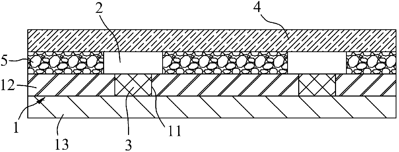
[0027] Such as figure 1 The integrated circuit integration structure shown includes a circuit substrate 1 and electronic components 2 arranged on the circuit substrate 1. The circuit substrate 1 can be set in different shapes according to needs, and the electronic components 2 can be set in different types according to the needs of circuit functions. and different quantities. The thermal conduction hole 11 is provided on the circuit substrate 1 , and is correspondingly arranged in different shapes according to the shape of the electronic component 2 , such as a circle or a square. The heat conduction holes 11 are correspondingly located below each electronic component 2, and the heat conduction holes 11 are filled with a heat conduction insulating layer 3, which is made of silicone grease, and heat conduction silica gel or heat conduction resin can also be used. The heat conduction insulation layers 3 correspond to their respective positions. The electronic components 2 are i...

Embodiment 2

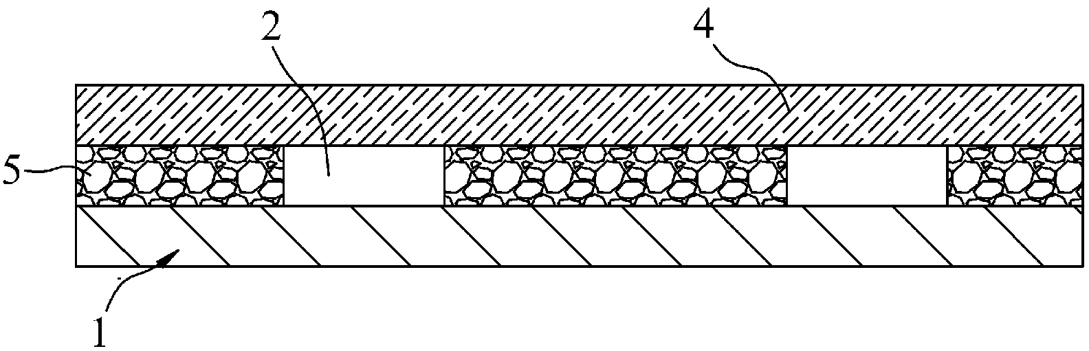
[0031] Such as figure 2 Shown is the second embodiment of the integrated circuit integration structure of the present invention. The difference between the second embodiment and the first embodiment is that the circuit substrate 1 is set as a ceramic substrate, which can reduce the volume of the structure and adapt to the narrow environment.

Embodiment 3

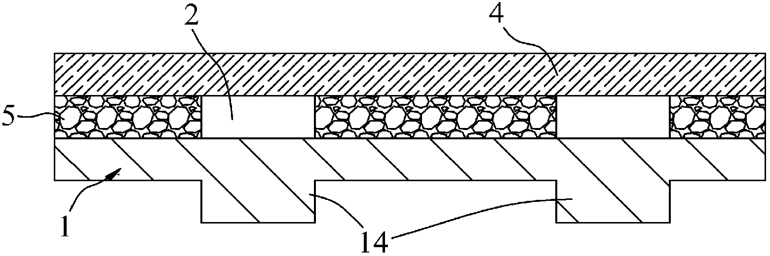
[0033] Such as image 3 Shown is the third embodiment of the integrated circuit integration structure of the present invention. The difference between the third embodiment and the second embodiment is that the lower end of the circuit substrate 1 has end pins 14 for auxiliary heat dissipation, and each end pin 14 is a One pair is located below the heat conduction hole 11 , conducts heat to the outside through the end pin 14 , and enhances the heat dissipation effect.


PUM


Abstract

The invention discloses an integration circuit integrated structure which comprises a circuit substrate and electronic components arranged on the circuit substrate. Heat conduction holes are formed in the circuit substrate. Each heat conduction hole is correspondingly located below each electronic component. Each heat conduction hole is respectively filled with a heat conduction insulating layer. Each heat conduction insulating layer is in contact with each electronic component corresponding to the position of each heat conduction insulating layer. Each electronic component can transfer and dissipate heat through each heat conduction insulating layer arranged below each electronic component so that heat of each electronic component is specially dissipated with pertinence. The integration circuit integrated structure is good in heat dissipation effect, capable of prolonging service life, improving efficiency and meanwhile playing the role of insulation and low in cost.

Description

technical field [0001] The invention relates to the technical field of printed circuits, in particular to an integrated circuit integration structure with good heat dissipation function. Background technique [0002] When electronic components are used in integrated circuits, they must have good heat conduction and heat dissipation methods in order to achieve longevity. The general heat conduction and heat dissipation methods are mainly: using aluminum substrates and ceramic substrates as circuit substrates to perform dual functions of conduction and heat conduction, or using Ordinary printed circuit boards and heat sinks and fans are added to the devices to be dissipated. [0003] However, when the aluminum substrate is used, the withstand voltage cannot meet the safety certification requirements, so an isolated power supply must be used, resulting in low power supply efficiency and high cost; if a ceramic substrate is used, although the withstand voltage can meet the safet...

Claims


Application Information

Patent Timeline
IPC IPC(8): H01L23/367H05K7/20
Inventor 余原生中野幸史付强
Owner 余原生
Why Eureka
Try Eureka