Check patentability & draft patents in minutes with Patsnap Eureka AI!

A method of high-precision time transfer using e1 special line

A time transfer, high-precision technology, applied in multiplex communication, time-division multiplex system, electrical components, etc., can solve the problem that the time stamp is not referable, not referable, and time synchronization error is large and other problems, to achieve the effect of no manual intervention, low cost and high reliability

Active Publication Date: 2015-10-14
CHENGDU GUOXING COMM
View PDF10 Cites 0 Cited by
  • Summary
  • Abstract
  • Description
  • Claims
  • Application Information

AI Technical Summary

Problems solved by technology

On the one hand, this method also realizes the calculation of the transmission delay by the slave device, and there is also the following problem: in the process of determining the transmission delay of obtaining the synchronization pulse, the receiving time information of the slave device needs to be used. However, this receiving time information It is obtained based on the local clock of the slave device, which itself has the problem of time asynchronization. Therefore, the delay is not referable when calculating the transmission, and the time synchronization error is large.
When recording the received packet timestamp T2, the timestamp is obtained based on the local clock of the slave station. Similarly, it has the problem of time asynchrony, so the obtained timestamp is not referable

Method used


Image

  • A method of high-precision time transfer using e1 special line
  • A method of high-precision time transfer using e1 special line
  • A method of high-precision time transfer using e1 special line

Examples


Embodiment Construction

[0029] The technical solution of the present invention will be further described in detail below in conjunction with the accompanying drawings, but the protection scope of the present invention is not limited to the following description.

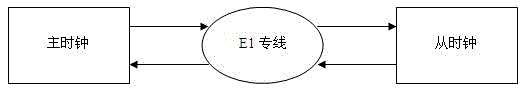
[0030] Such as figure 1 , figure 2 and image 3 As shown, a method for high-precision time transfer using an E1 dedicated line includes the following steps:

[0031] S1: The master clock sends a synchronization header message to the slave clock through the E1 dedicated line every second. The synchronization header message includes time stamp information and time information, and the master clock records the sending time stamp t1 of the synchronization header message;

[0032] S2: After time ΔT1, the slave clock receives the synchronization header message sent by the master clock, and forwards the synchronization header message back to the master clock;

[0033] S3: After time ΔT2, the master clock receives the synchronization header mes...


PUM


Abstract

The invention discloses a method for carrying out high-accuracy time transfer by utilizing an E1 special line. The method comprises the following steps that: a master clock sends synchronous head messages to a slave clock at a moment t1; the slave clock receives the synchronous head messages and forwards the synchronous head messages back to the master clock; the master clock receives the forwarded synchronous head messages at a moment t2; the master clock measures a time interval between the sending time and the receiving time of the synchronous head messages: t2-t1=deltaT1+deltaT2; the master clock sends a bidirectional time delay value to the slave clock through a broadcast message; the slave clock receives the broadcast message and extracts the bidirectional time delay value; the slave clock calculates single line transmission delay: deltaT=(deltaT1+deltaT2) / 2=(t2-t1) / 2; and the slave clock carries out time delay correction according to the single line transmission delay. According to the method for carrying out the high-accuracy time transfer by utilizing the E1 special line, the correction process does not involve the receiving time information of the slave clock, the time non-synchronization existing in the slave clock is avoided, the accuracy of the time synchronization is improved, and the accuracy of the time transfer can be controlled at about 10 nanoseconds; and compared with a conventional unidirectional time delay calculation method, the method provided by the invention has the advantages that the accuracy and the reliability of the time synchronization are further improved.

Description

technical field [0001] The invention relates to a method for high-precision time transfer by using an E1 dedicated line. Background technique [0002] With the development of communication technology, the requirements for time synchronization in the process of digital communication are getting higher and higher. In electric power and railway systems, the time used by most terminal equipment is provided by independent system internal clocks. Due to the differences in the internal clocks of each system, after the system has been running for a long time, there will be a large gap between the systems. This will bring huge safety hazards to the production and operation of electric power and railway systems. [0003] The 30-channel pulse code modulation PCM in Europe is referred to as E1. A time division multiplexing frame of E1 (its length T=125us) is divided into 32 equal time slots. The number of time slots is CH0~CH31, and the time slot CH0 is used as Frame synchronization, ...

Claims


Application Information

Patent Timeline
Patent Type & Authority Patents(China)
IPC IPC(8): H04J3/06
Inventor 周波孙新宇杨波
Owner CHENGDU GUOXING COMM
Features
  • R&D
  • Intellectual Property
  • Life Sciences
  • Materials
  • Tech Scout
  • Unparalleled Data Quality
  • Higher Quality Content
  • 60% Fewer Hallucinations
Learn More