
Photovoltaic cells

A photovoltaic device, conductivity type technology, applied in the field of photovoltaic cells, can solve problems such as low manufacturing cost

Inactive Publication Date: 2013-07-10
INTEGRATED PHOTOVOLTAICS
View PDF14 Cites 0 Cited by
  • Summary
  • Abstract
  • Description
  • Claims
  • Application Information

AI Technical Summary

Problems solved by technology

None of the cited prior art effectively addresses the main problem of solar cells, which is low manufacturing cost combined with commercial-grade conversion efficiencies; solar cell modules must cost less than $0.50 / watt to achieve parity with traditional usage pricing
Contents of the invention

Method used


Image

  • Photovoltaic cells
  • Photovoltaic cells
  • Photovoltaic cells

Examples


Embodiment Construction

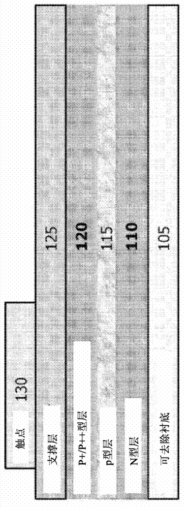
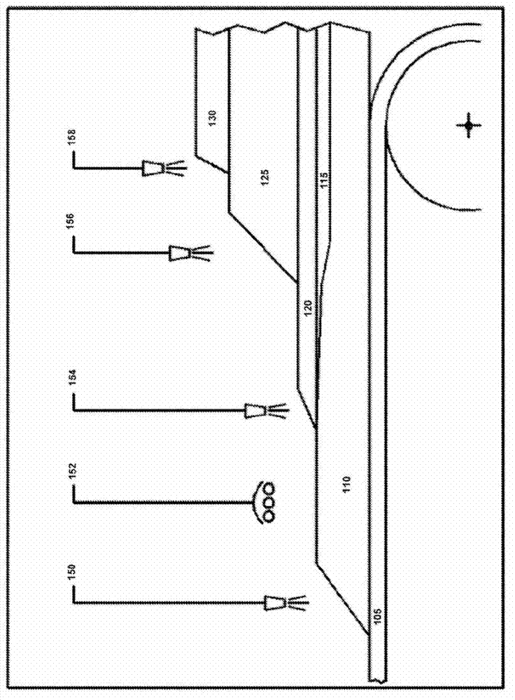
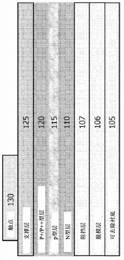
[0016] In some embodiments, as shown in FIG. 1 , on a flexible, supported material such as stainless steel sheet, graphite foil, graphite-coated flexible foil, graphite-coated stainless steel sheet, or other material suitable for roll-to-roll deposition, 1. Depositing a high-purity n-type silicon layer 110 on the removable substrate 105 . The thickness of the high purity n-type silicon layer may range from about 0.01 microns to greater than 100 microns. A release layer 106, such as silicon nitride, may be applied to the flexible substrate prior to depositing the n-type silicon layer on the flexible, supporting, removable substrate. Deposition processes 150 and 154 may be any method or combination of methods including CVD, PVD, MOCVD, PECVD, RF-PECVD, and high purity plasma spraying, among other processes known to those skilled in the art.

[0017] In some embodiments, the deposited n-type silicon layer is then recrystallized to form the light absorbing layer of the solar cell...


PUM


Abstract

An inline process for manufacturing a photovoltaic device on a removable substrate is disclosed. The process discloses two semiconductor layers forming an active region; at least one of the semiconductor layers is formed by a high-purity plasma spray process; optional layers include a release layer, one or more barrier layers, a cap layer, a conductive support layer, a mechanical support layer, an anti-reflection layer, and distributed Bragg reflector. The process may also be used to form multiple active regions.

Description

[0001] priority [0002] This application claims priority to US Provisional Application Nos. 61 / 235,610 and 61 / 239,739, filed August 20, 2009 and September 3, 2009, respectively. [0003] Cross References to Related Applications [0004] This application is related in part to U.S. Application Serial Nos. 11 / 782,201, 12 / 074,651, 12 / 720,153, 12 / 749,160, 12 / 789,357, 61 / 235,610, 61 / 239,739, and filed August 20, 2010 entitled "Photovoltaic Cell on Substrate (Photovoltaic Cells on a Substrate), U.S. Application Serial No. 12 / 860,048, all of which are owned by the same assignee and are incorporated herein by reference in their entirety. Additional technical explanations and background are cited in the reference material. Background technique [0005] 1. Domain [0006] The technology relates primarily to photovoltaic devices formed by depositing semiconductor-based layers on removable substrates. 2. Description of related technologies [0007] The prior art in this field includ...

Claims


Application Information

Patent Timeline
IPC IPC(8): H01L31/18H01L31/042
CPCH01L31/02165H01L31/02168H01L31/028H01L31/0296H01L31/0304H01L31/03685H01L31/03762H01L31/03765H01L31/0392H01L31/03921H01L31/056H01L31/1872H01L31/1892H01L31/1896H01L31/206Y02E10/52Y02E10/544Y02E10/545Y02E10/547Y02E10/548Y02P70/50
Inventor 沙伦·泽哈维杰尔姆·S·丘利克
Owner INTEGRATED PHOTOVOLTAICS
Learn More