Pulse tube expansion machine

A technology of expanders and pulse tubes, applied in compressors, refrigerators, compressors, etc., can solve problems such as accompanying losses in the expansion process, achieve high feasibility, improve energy utilization efficiency, and improve efficiency

Active Publication Date: 2013-07-17
朱绍伟
View PDF7 Cites 10 Cited by
  • Summary
  • Abstract
  • Description
  • Claims
  • Application Information

AI Technical Summary

Problems solved by technology

At the beginning, the vapor pressure of the evaporation is very high, and this part of the vapor is finally expanded to a low pressure, and is compressed to a high pressure without participating in the refrigeration process. The expansion process is accompanied by losses, and the compression process is also accompanied by losses.

Method used


Image

  • Pulse tube expansion machine
  • Pulse tube expansion machine
  • Pulse tube expansion machine

Examples


Embodiment 1

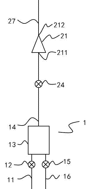
[0025] Such as figure 1 As shown, there is an inflow pipeline 11 and an inflow valve 12 on the pulse tube 13, an outflow pipeline 16 and an outflow valve 15, an outlet pipeline 14 is arranged, and an outlet valve 24 is arranged on the outlet pipeline 14, and the outlet pipeline 14 is connected to the low-pressure end 211 of the compressor 21. Connected, the high-pressure end 212 of the compressor 21 is connected with the expansion gas outflow pipeline 27, the pulse tube 13 is a cavity or empty pipe with a certain volume, and the expansion gas outflow pipeline 27 is an external output port, which can make the expander output the compressed air outward. used steam for other purposes.

[0026] Such as figure 1 As shown, the working process is as follows:

[0027] Liquid inlet process: the outflow valve 15 is closed and the inflow valve 12 is opened. The high-pressure liquid to the vessel 13 through the inflow pipe 11 flows into the lower end of the vessel 13 . When th...

Embodiment 2

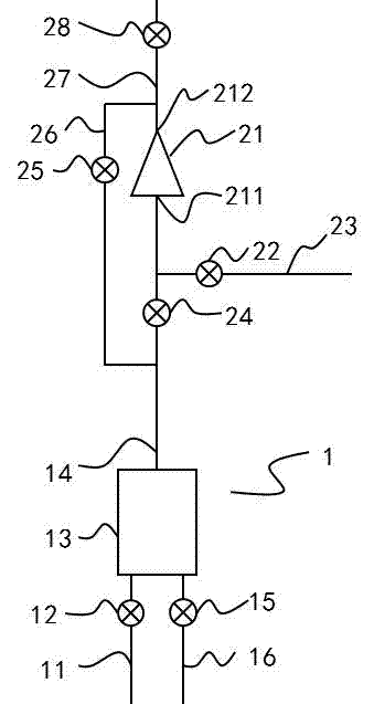
[0041] Such as image 3 As shown, a low-pressure bypass pipe 23 is added to the low-pressure end of the compressor 21, and a low-pressure bypass valve 22 is arranged on it, and a high-pressure bypass pipe 26 connects the high-pressure end and the low-pressure end of the compressor 21, and there is a high-pressure bypass Road valve 25. An inflation gas outflow valve 28 is installed on the inflation gas outflow pipeline 27 . Here, the low-pressure bypass pipe 23 communicates with the outside world, allowing the compressor to suck low-pressure steam.

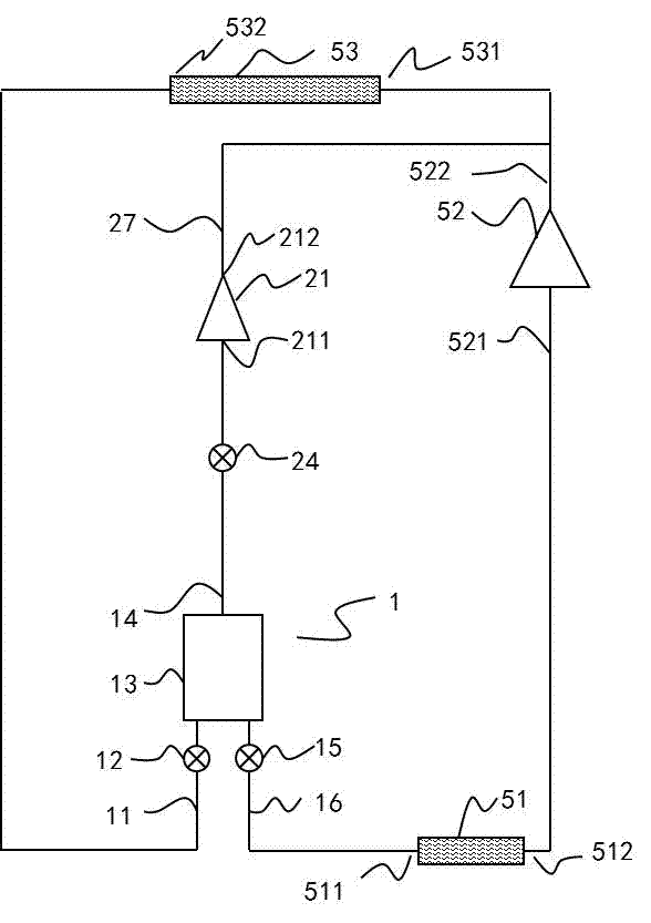
[0042] Such as Figure 4 As shown, the low-pressure bypass pipe 23 is connected to the low-pressure pipe 521 .

[0043] In this embodiment, the compressor 21 is always on. But it can also be stopped when the valve is switched.

[0044] Such as image 3 As shown, the working process of the expander 1 is as follows:

[0045] Liquid inlet process: the low-pressure bypass valve 22 is closed, the high-pressure bypass va...

Embodiment 3

[0064] see Figure 5 , add high-pressure gas discharge pipeline 32 and low-pressure gas inlet pipeline 34 on the top of pulse tube, high-pressure gas discharge valve 31 is arranged on high-pressure gas discharge pipeline 32, low-pressure gas inlet valve 33 is arranged on low-pressure gas inlet pipeline 34. Before the inflow valve 12 , the high-pressure liquid storage tank 55 and the auxiliary condenser 551 are connected through the inflow pipe 11 , and the high-pressure liquid storage tank 55 is connected to the condenser liquid outlet pipe 54 . After the outflow valve 15 is connected to the low-pressure liquid storage tank 56 through the outflow pipe 16, the low-pressure liquid storage tank 56 is connected with an evaporator liquid inlet pipe 59. The low-pressure gas inlet pipe 34 is connected to the top of the low-pressure liquid storage tank 56 , and the high-pressure gas discharge pipe 32 is connected to the top of the high-pressure liquid storage tank 55 .

[0065] se...


PUM


Abstract

The invention relates to a pulse tube expansion machine and a heat pump or a refrigerating machine comprising the pulse tube expansion machine. The pulse tube expansion machine comprises a pulse tube (13) and a compressor (21), an inflow pipeline (11) and an outflow pipeline (16) are arranged on the pulse tube (13), a low-pressure end (211) of the compressor (21) is connected with the pulse tube (13), and a high-pressure end (212) of the compressor (21) is connected into a high-pressure pipeline (522) of an external circulation system. Steam evaporated from high-pressure liquid in the pulse tube (13) is conveyed to the external high-pressure pipeline after extracted and compressed by the compressor (21), and the pressure in the pulse tube continuously reduces along with continuous extraction of the steam, so that the liquid expansion process is realized. In the process, the steam cannot be expanded to have low pressure, is directly compressed to have high pressure and is outputted for other purposes, so that the steam expansion process is avoided, energy use efficiency is improved, and the pulse tube expansion machine can be used for the heat pump or the refrigerating machine and the like to replace a throttling valve.

Description

technical field [0001] The invention relates to a heat pump or a refrigerator, in particular to a pulse tube expander used in the circulation system of the heat pump or refrigerator. Background technique [0002] Heat pump technology is a new energy technology that has attracted much attention in recent years, which can transfer the thermal energy of a low-temperature heat source to a high-temperature heat source. A heat pump works in cooling mode, i.e. has the same function as a chiller. In the circulation system of a heat pump or a refrigerator, it is necessary to convert a high-pressure fluid in a high-pressure state into a low-pressure fluid. [0003] An expander is a device that changes a high-pressure fluid into a low-pressure fluid, lowers the temperature of the fluid, and recovers or converts the expansion work of the fluid into other forms of energy. The single-phase expander is a very mature technology, but the expander that vaporizes the high-pressure liquid dur...

Claims


Application Information

Patent Timeline
Patent Type & Authority Applications(China)
IPC IPC(8): F25B9/14F25B31/00
Inventor 朱绍伟
Owner 朱绍伟
Why Eureka
Try Eureka