Piezoelectric tension monitoring device

A monitoring device, piezoelectric technology, applied in the direction of tension measurement, etc., can solve the problems of small beam pre-camber, small component pre-stress, pressure sensor can not be reused, etc., to achieve good stability and high measurement accuracy.

Inactive Publication Date: 2013-07-17
CHANGAN UNIV
View PDF5 Cites 4 Cited by
  • Summary
  • Abstract
  • Description
  • Claims
  • Application Information

AI Technical Summary

Problems solved by technology

Due to factors such as the slippage of the prestressed tendons, the shrinkage of the prestressed tendon, and the friction loss of the anchor mouth during the anchoring process of the YJM anchorage, there is obviously an error in the value of the control tension. If the error is too large, the prestress of the component will be less than the design value. Thus leaving engineering hidden dangers (accidents with small pre-compression stress values ​​often occur in engineering construction, resulting in small pre-camber of girders, cracking of components in severe cases, etc.)
In order to ensure the quality of the project, accurately obtain the size of the anchoring force, and reasonably estimate the anchoring force loss value of the YJM anchorage during the anchoring process due to the slippage, shrinkage of the prestressed tendon, and the friction loss of the anchor mouth. A pressure sensor is installed between the anchor plate and the anchor to accurately measure the anchoring force value, but this method can only be used for research and cannot be widely promoted in engineering, because first, the pressure sensor will occupy space, which will change the structural geometry Size design; second, the pressure sensor cannot be reused, thus increasing the project cost, because each pressure sensor ranges from several hundred yuan to several thousand yuan

Method used


Image

  • Piezoelectric tension monitoring device
  • Piezoelectric tension monitoring device
  • Piezoelectric tension monitoring device

Examples


Embodiment 1

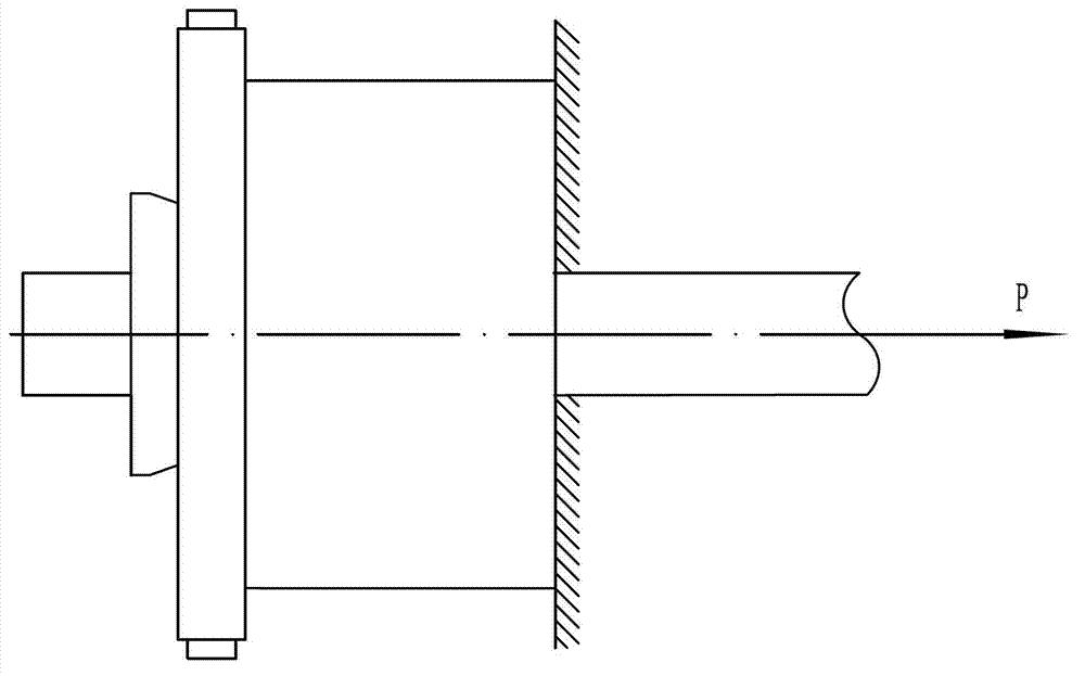
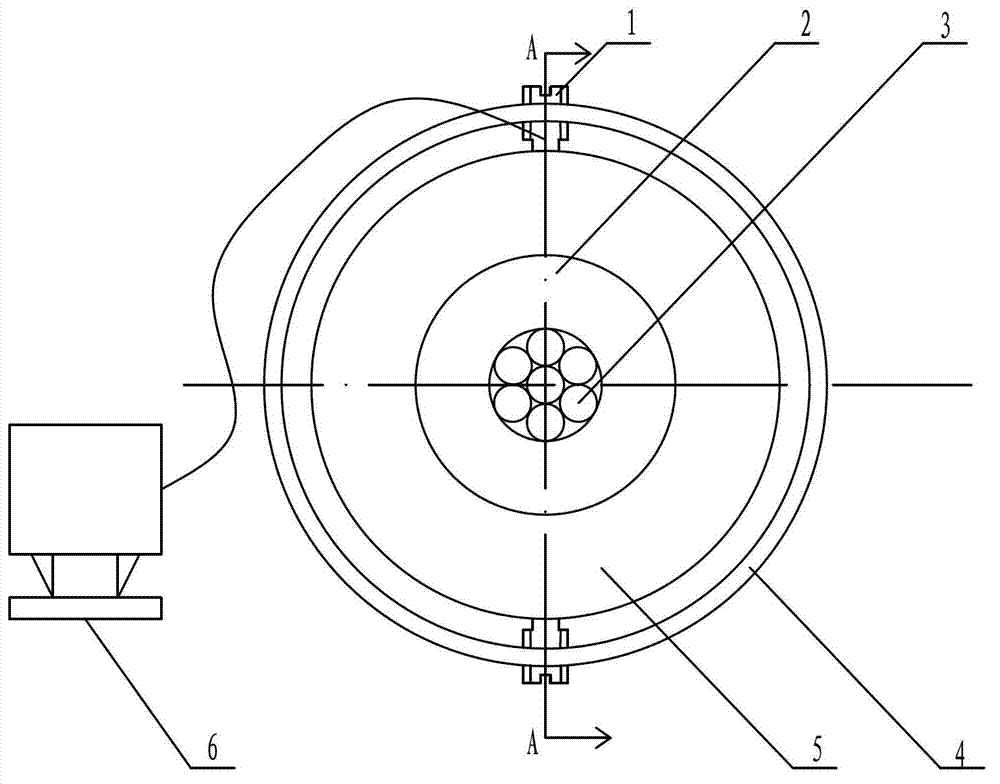
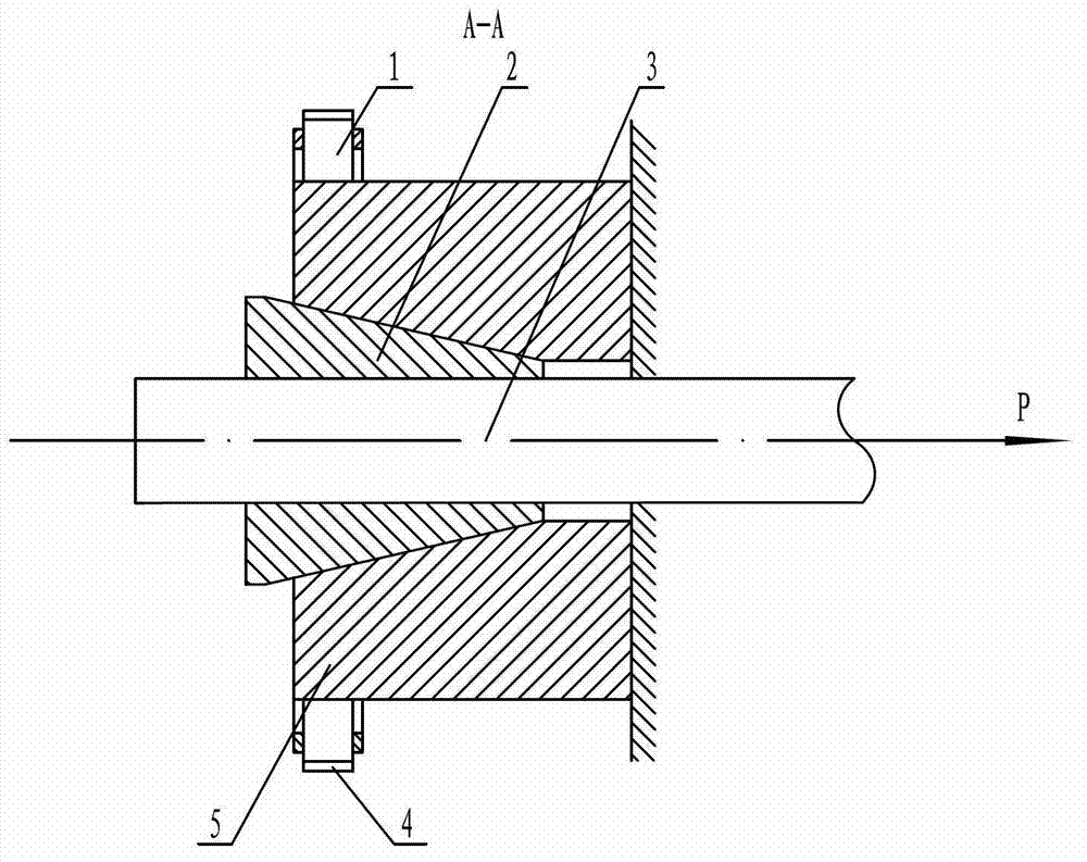
[0016] exist figure 1 , 2 , 3, the piezoelectric tension monitoring device of this embodiment is composed of a piezoelectric sensor 1, a clip 2, a steel strand 3, a ring 4, an anchor ring 5, and a computer 6 connected.

[0017] A clip 2 is installed outside the steel strand 3 to be tested, and the cone angle of the clip 2 is 15°. An anchor ring 5 is set on the outside of the clip 2. The geometry of the clip 2 and the anchor ring 5 is the same as that of the existing project. The anchorage used in is the same, the center of the anchor ring 5 is processed with a center hole, the center hole is a tapered hole, and the taper of the center hole is the same as that of the clip 2. Anchor ring 5 is covered with a ring 4, and two piezoelectric sensors 1 are installed on the ring 4 between the outer surface of the ring 4 and the outer surface of the anchor ring 5 through threads. The centerlines of the two piezoelectric sensors 1 are on the same diameter. The two piezoelectric sensor...

Embodiment 2

[0021] In this embodiment, a circular ring 4 is sheathed on the anchor ring 5. Between the circular ring 4 and the outer surface of the anchor ring 5, three piezoelectric sensors 1 are installed on the circular ring 4 through threads. The included angle between the centerlines of the electric sensors 1 is 120°, the structure of the piezoelectric sensors 1 is the same as in embodiment 1, and the three piezoelectric sensors 1 will receive the tensile force and steel strands 3 that are borne by the steel strands 3. The pressure received by the deformation of the anchor ring 5 caused by the clip 2 is converted into an electrical signal and output to the computer 6, and the computer 6 performs calculations according to a preset program to calculate the tension force of the steel strand 3. Other components and the coupling relationship of the components are the same as in Embodiment 1.

Embodiment 3

[0023] In this embodiment, a circular ring 4 is sheathed on the anchor ring 5, and four piezoelectric sensors 1 are installed on the circular ring 4 through threads evenly distributed between the circular ring 4 and the outer surface of the anchor ring 5. The included angle between the centerlines of the electric sensors 1 is 90°, the structure of the piezoelectric sensors 1 is the same as in embodiment 1, and the four piezoelectric sensors 1 will receive the tensile force borne by the steel strands 3, the steel strands 3 The pressure received by the deformation of the anchor ring 5 caused by the clip 2 is converted into an electrical signal and output to the computer 6, and the computer 6 performs calculations according to a preset program to calculate the tension force of the steel strand 3. Other components and the coupling relationship of the components are the same as in Embodiment 1.


PUM

PropertyMeasurementUnit
angleaaaaaaaaaa
angleaaaaaaaaaa
angleaaaaaaaaaa

Abstract

The invention discloses a piezoelectric tension monitoring device. A clamping sheet is arranged outside one tested stranded wire or each of 3-5 tested stranded wires, wherein an anchor ring is arranged outside the clamping sheet, a ring is arranged outside the anchor ring, at least two piezoelectric sensors dividing a circumference in equal parts are arranged between the ring and the outer surface of the anchor ring, the piezoelectric sensors are connected with a computer through data wires, and convert the received pressure born by the stranded wire and the pressure born by the stranded wire due to the deformation of the anchor ring through the clamping sheet to electric signals to output to the computer, and the computer computes according to the program set in advance to calculate the tension of the stranded wire. The device disclosed by the invention has the advantages of good stability, high measurement precision, and capability of repeated use, and can be applied to monitoring the tension of the stranded wire when constructing a pre-stressed concrete structure project.

Description

technical field [0001] The invention belongs to the technical field of force measuring equipment or devices, and in particular relates to a testing instrument for an anchorage steel strand assembly. Background technique [0002] At present, prestressing technology is widely used in civil engineering. In the construction of prestressed concrete structures, most of them adopt the post-tensioning method: that is, the component concrete is poured first, and holes are reserved or casings are buried in it. After the concrete reaches the required strength, at least one or more steel strands are inserted into the reserved tunnel, supported on the end of the concrete component by a jack, and the steel strand is stretched, so that the component is simultaneously compressed by the counter force, and the tension is maintained. To control the tension, the size of the control tension is indirectly measured by the oil pressure gauge on the tensioning equipment, that is, the steel strand is...

Claims


Application Information

Patent Timeline
Patent Type & Authority Applications(China)
IPC IPC(8): G01L5/10
Inventor 王建华陈峰任更锋贾利强张焕涛
Owner CHANGAN UNIV
Why Eureka
Try Eureka