
Battery sensor

A battery sensor and battery technology, applied in the direction of instruments, components of electrical measuring instruments, measuring electricity, etc., can solve problems such as limiting the maximum measurement range of battery sensors, and achieve the effect of optimizing energy distribution and reducing costs

Inactive Publication Date: 2013-07-17
ROBERT BOSCH GMBH
View PDF1 Cites 2 Cited by
  • Summary
  • Abstract
  • Description
  • Claims
  • Application Information

AI Technical Summary

Problems solved by technology

So resistance tolerance may limit the maximum measurement range of this battery sensor

Method used


Image

  • Battery sensor

Examples


Embodiment Construction

[0028] The invention is shown schematically in the drawing with the aid of an embodiment and is explained in more detail below with reference to the drawing.

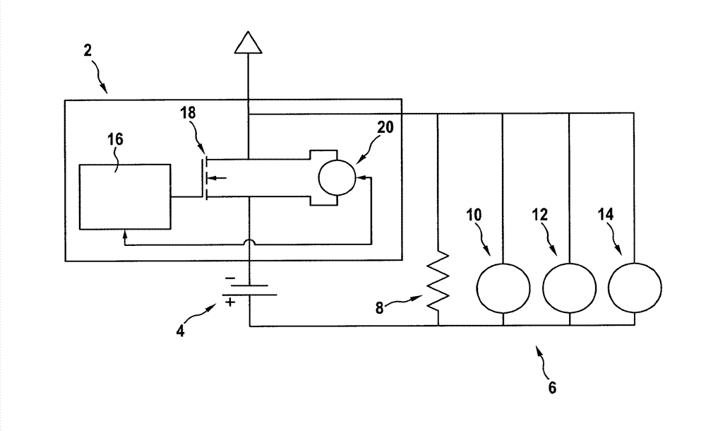
[0029] FIG. 1 shows a schematic diagram of an embodiment of a battery sensor 2 according to the invention, which is designed to measure at least one operating parameter of a battery 4 . It is provided here that the battery 4 is designed as part of an on-board electrical system 6 of the motor vehicle. The vehicle electrical system 6 also contains an additional ohmic load 6 , at least one electric motor 10 , that is to say, for example, one or more electric motors 10 for electric power steering assistance, a generator 12 and a load 14 designed as a starter. .

[0030]Battery sensor 2 contains logic evaluation, control and regulation device 16 , which is designed here as an electronic circuit, in which an algorithm is implemented for determining at least one operating parameter of battery 4 . Evaluation device 16 is desi...


PUM


Abstract

The invention relates to a battery sensor for determining at least one operational parameter of a battery (4), wherein the battery sensor (2) comprises at least one transistor (18) having controllable resistance, which is designed to determine the at least one operational parameter.

Description

technical field [0001] The invention relates to a battery sensor and a method for determining at least one operating parameter of a battery. Background technique [0002] Current accurate battery sensors use passive resistive materials for current measurement, usually with manganin for the desired temperature stability. In this case, the voltage drop of the battery is detected by means of a resistor made of manganese copper, which is designed as a shunt, as part of the battery sensor. In addition, the flowing current is determined. The shunt is usually designed here as 100 μohm. The resistance value determined during the development of the battery sensor can no longer be changed during its lifetime. Resistance tolerances may therefore limit the maximum measurement range of this battery sensor. [0003] The requirements for identifying the state of energy stores designed as batteries are increasing. For the measurement, the method of impedance spectroscopy can also be us...

Claims


Application Information

Patent Timeline
Patent Type & Authority Applications(China)
IPC IPC(8): G01R31/36G01R19/00
CPCG01R19/0092G01R1/203G01R31/3644G01R31/3606G01R31/382
Inventor M.布雷默
Owner ROBERT BOSCH GMBH
Learn More