High-voltage direct-current circuit breaker based on double switches

A high-voltage direct current, double-switch technology, applied in the direction of electric switches, circuits, electrical components, etc., can solve the problems that the DC system does not have the zero crossing point of the AC system, the vacuum switch tube is bulky, and the relay cannot be disconnected, etc., to achieve small size, Long service life, no leakage current effect

Active Publication Date: 2013-07-17
ZHONGTIAN TECH MARINE SYST CO LTD
View PDF4 Cites 15 Cited by
  • Summary
  • Abstract
  • Description
  • Claims
  • Application Information

AI Technical Summary

Problems solved by technology

[0002] The current DC power supply system is more and more widely used, and the DC circuit breaker is an indispensable key component of the DC power supply system. However, the DC system does not have the characteristics of the zero-crossing point of the AC system. The air between the heads is easily ionized to generate an arc. The higher the voltage, the more obvious the ionization phenomenon, which can easily damage the contacts and cause the relay to fail to disconnect the load.
Therefore, the current DC circuit breakers mainly include mechanical relays used in low voltage (tens of volts), and vacuum switch tubes used in high voltage (above thousands of volts). Huge in size, complicated in structure and expensive in price, neither of them are suitable for controlling DC circuit breakers in the range of hundreds of volts to thousands of volts

Method used


Image

  • High-voltage direct-current circuit breaker based on double switches
  • High-voltage direct-current circuit breaker based on double switches

Examples


Embodiment Construction

[0011] Further illustrate the present invention below in conjunction with accompanying drawing.

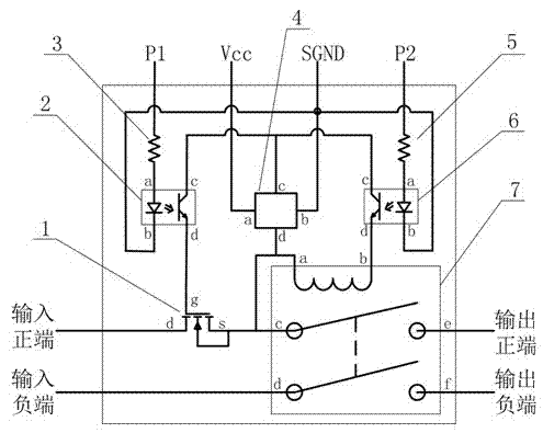
[0012] Such as figure 1 As shown, a high-voltage DC circuit breaker based on a double switch includes a semiconductor switch tube 1, a switch tube control optocoupler 2, a switch tube control resistor 3, an isolated power supply 4, a relay control resistor 5, a relay control optocoupler 6, and double-pole double-throw Relay 7, the switch tube controls the output terminal b of the light-emitting diode in the optocoupler 2 and is connected to the output terminal b of the light-emitting diode in the relay control optocoupler 6, and the switch tube controls the input terminal a of the light-emitting diode in the optocoupler 2 and the switch tube controls the resistor 3 The other end P1 of the switch tube control resistor 3 is the semiconductor switch tube control end, the input terminal a of the light-emitting diode in the relay control optocoupler 6 is connected to one end of the rel...


PUM


Abstract

The invention discloses a high-voltage direct-current circuit breaker based on double switches. The high-voltage direct-current circuit breaker comprises a semi-conductor switch tube, a switch tube control optocoupler, a switch tube control resistor, an isolation power supply, a relay control resistor, a relay control optocoupler and a double-pole double-throw relay. The semi-conductor switch tube is connected with a positive end of a high-voltage direct-current power transmission line in series. The double-pole double-throw relay has two accesses, one access is connected with the positive end of the high-voltage direct-current power transmission line in series and connected behind the semi-conductor switch tube in cascade mode, and the other access is connected with a negative end of the high-voltage direct-current power transmission line in series. The output ends of the two accesses of the double-pole double-throw relay are respectively the output positive end and the output negative end of the high-voltage direct-current power transmission line. Connection and disconnection of the semi-conductor switch tube are controlled by the switch tube control optocoupler, and connection and disconnection of the two accesses of the double-pole double-throw relay are controlled by the relay control optocoupler. The circuit breaker is small in size, fast in connection and disconnection, free of leakage current and safe and reliable to use.

Description

technical field [0001] The invention relates to a high-voltage direct current circuit breaker based on a double switch type, which is a key technology for on-off control of a high-voltage direct current power supply system. Background technique [0002] The current DC power supply system is more and more widely used, and the DC circuit breaker is an indispensable key component of the DC power supply system. However, the DC system does not have the characteristics of the zero-crossing point of the AC system. The air between the heads is easily ionized to generate an arc. The higher the voltage, the more obvious the ionization phenomenon, which can easily damage the contacts and cause the relay to fail to disconnect the load. Therefore, the current DC circuit breakers mainly include mechanical relays used in low voltage (tens of volts), and vacuum switch tubes used in high voltage (above thousands of volts). The volume is huge, the structure is complicated, and the price is e...

Claims


Application Information

Patent Timeline
Patent Type & Authority Applications(China)
IPC IPC(8): H01H9/54
Inventor 陈燕虎杨灿军张锋裴跃飞李德骏金波
Owner ZHONGTIAN TECH MARINE SYST CO LTD
Why Eureka
Try Eureka