AI technical title is built by Patsnap AI team. It summarizes the technical point description of the patent document.
A band-pass filter, optical multilayer film technology, applied in optics, optical components, instruments, etc., to reduce polarization dependence and eliminate ghosting effects
Active Publication Date: 2013-07-17
OLYMPUS CORP
View PDF4 Cites 7 Cited by
Summary
Abstract
Description
Claims
Application Information
AI Technical Summary
This helps you quickly interpret patents by identifying the three key elements:
Problems solved by technology
Method used
Benefits of technology
Problems solved by technology
Therefore, the transmission characteristic of p-polarized light becomes a wider form compared with the transmission characteristic of s-polarized light, and there may be practical problems
Method used
Image
Click on the blue label to locate the original text in one second.
Reading with bidirectional positioning of images and text.
Examples
Embodiment 1)
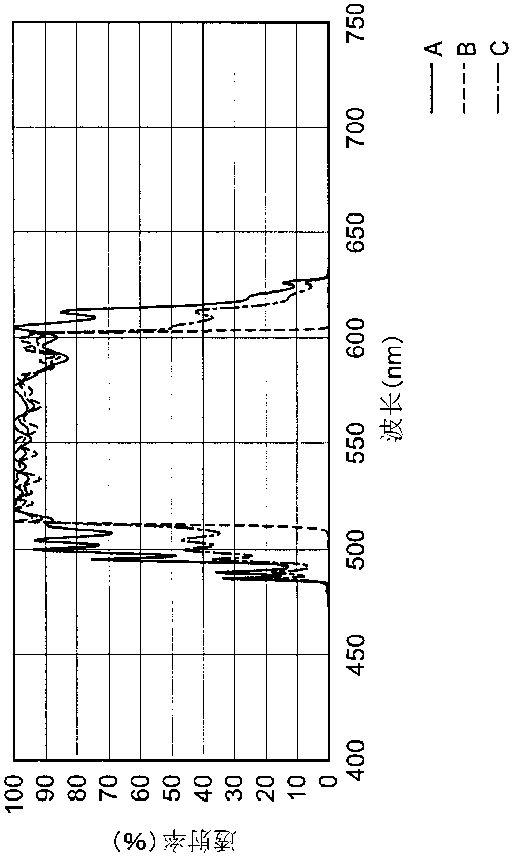
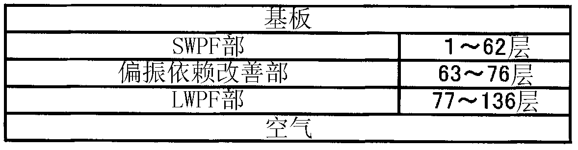
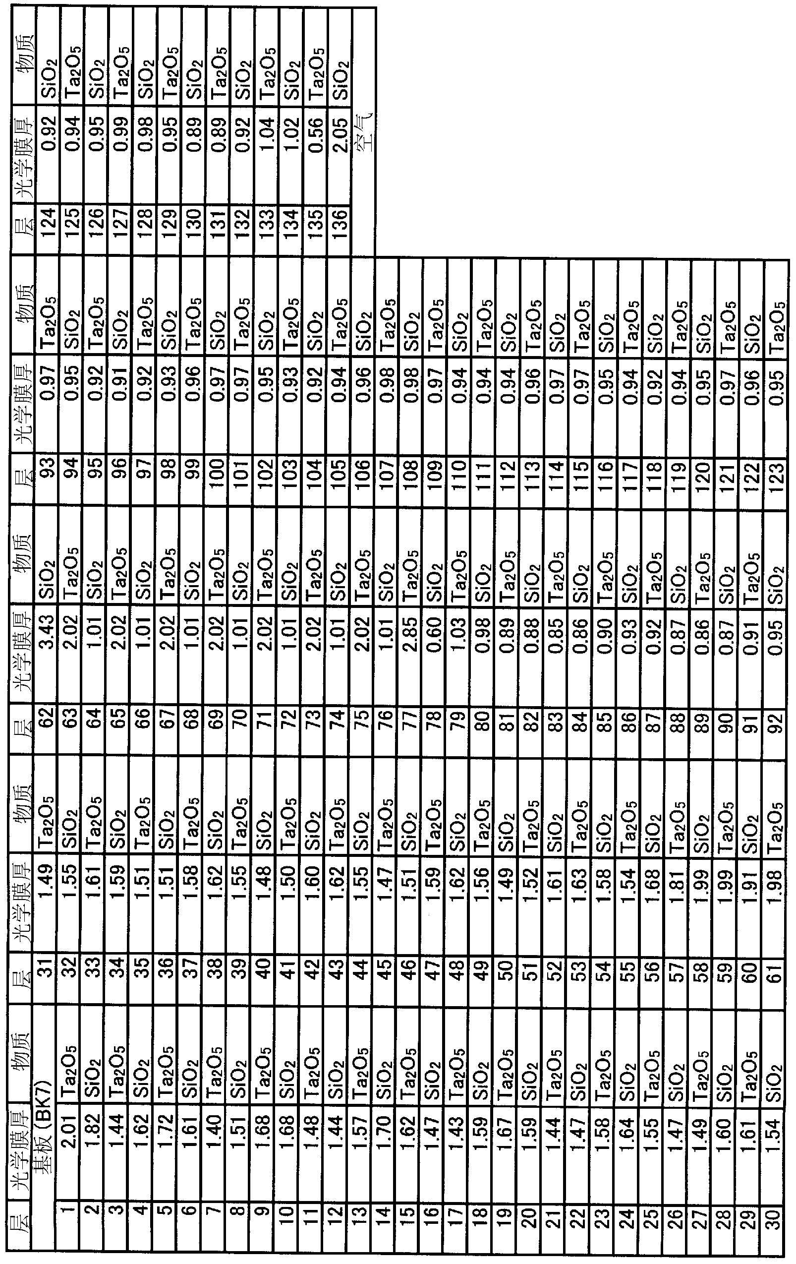
[0099] figure 1 It is a graph showing the bandpass characteristic of the optical multilayer film bandpass filter of Example 1. figure 2 It is a sectional view showing the structure of the optical multilayer film bandpass filter of Example 1. image 3 It is a graph showing the film thickness and constituent substances of each layer of the optical multilayer film bandpass filter of Example 1. exist figure 1 Among them, the solid line A represents the p-polarized light transmission characteristic (Tp), the dotted line B represents the s-polarized light transmission characteristic (Ts), and the dotted line C represents the average (Tmean) of the p-polarized light transmission characteristic and the s-polarized light transmission characteristic. and, in image 3 , shows the optical film thickness (λ / 4=1) when the incident angle is 45 degrees and the wavelength λ of the target light is 498 nm.
[0100] Such as figure 2 , image 3 As shown, the optical multilayer film bandp...
Embodiment 2~ Embodiment 5)
[0111] Figure 7 , Figure 11 , Figure 15 and Figure 19 It is a graph showing the bandpass characteristics of the optical multilayer film bandpass filters of Example 2, Example 3, Example 4, and Example 5, respectively.
[0112] Figure 8 , Figure 12 , Figure 16 and Figure 20 It is a graph showing the bandpass characteristics of the SWPF part, the LWPF part, and the polarization-dependent improvement part in Example 2, Example 3, Example 4, and Example 5, respectively.
[0113] Figure 9 , Figure 13 , Figure 17 and Figure 21 It is a sectional view showing the structure of the optical multilayer film bandpass filter of Example 2, Example 3, Example 4, and Example 5, respectively.
[0114] Figure 10 , Figure 14 , Figure 18 and Figure 22 It is a graph showing the film thickness and constituent substances of each layer of the optical multilayer film bandpass filters of Example 2, Example 3, Example 4, and Example 5, respectively.
[0115] exist Figure...
Embodiment 2
[0129] (1) Example 2: high refractive index layer > low refractive index layer ( Figure 7 )
PUM
Abstract
The present invention solves problems such as ghosts produced by dihedral reflection, with little dependence on polarized waves with respect to inclined incidence. An optical multilayered film bandpass filter is provided with: a transparent substrate facing target light; an LWPF unit which is formed on only one side of the substrate, and forms a rising section on the short wavelength side in the bandpass characteristics and a reflection band; an SWPF unit which forms a falling section on the long wavelength side in the bandpass characteristics and the reflection band; and a polarized-wave dependency improvement unit for controlling the separation of P waves and S waves produced by the inclined incidence of the target light in the rising section and the falling section respectively formed by the LWPF unit and the SWPF unit. The LWPF unit, the SWPF unit, and the polarized-wave dependency improvement unit are provided with a structure comprising a plurality of alternately laminated layers of high refractive indexlayers formed by a first dielectric body, and low refractive indexlayers formed by a second dielectric body having a lower refractive index than the first dielectric body.
Description
technical field [0001] The invention relates to an optical multilayer film bandpass filter. Background technique [0002] As for optical multilayer bandpass filters having a structure in which dielectric thin films with high and low refractive indices are laminated alternately on a glass substrate or the like, as general optical characteristics, there are "transmission bands" in which light of a certain wavelength range is transmitted, The "reflection band (or blocking domain)" that blocks light of a certain wavelength range before and after it, and the slope where the transmittance rises or falls at the boundary between the transmission band and the reflection band. In the following description, at the boundary between the transmission band and the reflection band, the slope where the transmittance rises on the short wavelength side is referred to as a "rising portion", and the slope where the transmittance decreases on the long wavelength side is called a "falling portion"...
Claims
Application Information
Patent Timeline
Application Date:The date an application was filed.
Publication Date:The date a patent or application was officially published.
First Publication Date:The earliest publication date of a patent with the same application number.
Issue Date:Publication date of the patent grant document.
PCT Entry Date:The Entry date of PCT National Phase.
Estimated Expiry Date:The statutory expiry date of a patent right according to the Patent Law, and it is the longest term of protection that the patent right can achieve without the termination of the patent right due to other reasons(Term extension factor has been taken into account ).
Invalid Date:Actual expiry date is based on effective date or publication date of legal transaction data of invalid patent.

