Orthodontic accelerator

An accelerator and orthodontic technology, applied in the field of orthodontic accelerators, can solve the problems of large ultrasonic energy consumption, complicated device for loading vibration force, narrow vibration frequency band, etc., to accelerate the generation and acceleration of osteoclasts and osteoblasts. The flow of blood, the effect of strong applicability

Active Publication Date: 2013-07-24
深圳尚瑞得科技有限公司
View PDF7 Cites 13 Cited by
  • Summary
  • Abstract
  • Description
  • Claims
  • Application Information

AI Technical Summary

Problems solved by technology

[0004] However, traditional orthodontic methods and accelerators have the following disadvantages: (1) The traditional orthodontic method of loading static force takes a long time, and the treatment cycle is two to three years
(2) The device for loading the vibration force is complicated, the operation is cumbersome, and the safety of the patient is difficult to guarantee
(3) Ultrasound consumes a lot of energy, it is difficult to miniaturize the device, and it cannot be carried around. The proportion of ultrasonic waves absorbed by teeth is also large, resulting in waste of energy and no benefit to the teeth themselves.
(4) It can only target one or two teeth, which cannot meet the needs of patients or is difficult to use
(5) The vibration frequency band is too narrow, the parameters cannot be adjusted, and the method of use is not clear
It is not possible to flexibly adjust parameters such as how long it is used every day and how much vibration force is required each time.

Method used


Image

  • Orthodontic accelerator
  • Orthodontic accelerator
  • Orthodontic accelerator

Examples


Embodiment Construction

[0028] The present invention will be further described below in conjunction with drawings and embodiments. It should be understood that the specific embodiments described here are only used to explain the present invention, but not to limit the present invention. In addition, it should be noted that, for the convenience of description, only parts related to the present invention are shown in the drawings but not all content.

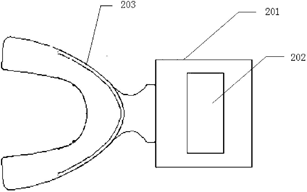
[0029] Please refer to figure 2 as shown, figure 2 The structure diagram of the orthodontic accelerator provided by the embodiment of the present invention.

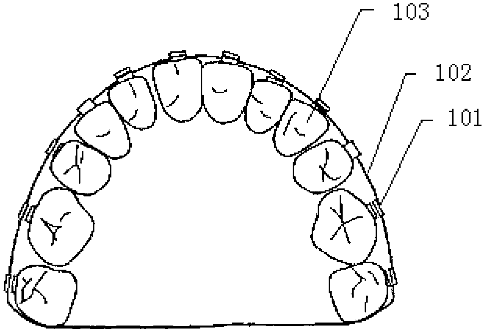
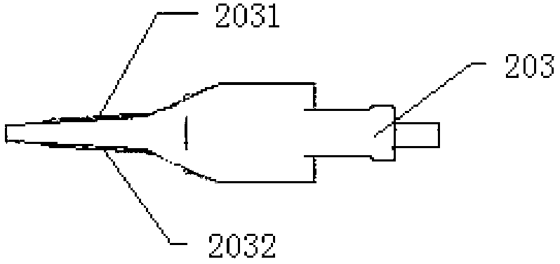
[0030] The orthodontic accelerator in this embodiment, commonly known as an orthodontic smile accelerator, includes a vibrator 201 , a display screen 202 and a dental tray 203 . The vibrator 201 is used to generate the vibration required for orthodontics. The dental tray 203 is connected with the vibrator 201 for transmitting the vibration to the teeth. The side view of the dental tray 203 i...


PUM


Abstract

The invention discloses an orthodontic accelerator commonly known as an orthodontic smiling accelerator. The orthodontic accelerator comprises a vibrator, a display screen and a denture. The vibrator is used to generate the vibration required by orthodontics. The denture is connected to the vibrator and used for transmitting the vibration to the teeth. The display screen is connected to the vibrator and used for displaying electric quantity of the vibrator and the number of adjuvant therapy. The orthodontic accelerator provided by the invention can accelerate movement of teeth in an orthodontic treatment process, and greatly reduce the time required for orthodontic treatment, without reducing the effect of an orthodontic operation.

Description

technical field [0001] The invention relates to the technical field of orthodontic treatment, in particular to an orthodontic accelerator. Background technique [0002] Since 1901, orthodontics, as a branch of stomatology, has experienced more than 100 years of development. In the first 30 years, the invention of the square wire appliance in North America laid the foundation for orthodontic treatment, which is still in use today. It uses stainless steel wires to tighten the teeth, and the static force generated by the wires acts on the teeth for a long time, so as to achieve the purpose of making the teeth, including their roots, move in a predetermined direction in the alveolar bone. With this method, after about two years of wearing (during which the doctor adjusts the magnitude and direction of the force loaded by the wire according to the movement of the teeth), most patients can have a pair of beautiful teeth and a bright smile. In the next few decades, people will co...

Claims


Application Information

Patent Timeline
Patent Type & Authority Applications(China)
IPC IPC(8): A61C7/00
Inventor 毛剑尚鹏
Owner 深圳尚瑞得科技有限公司
Why Eureka
Try Eureka