
Ampere force driving micro spraying device

A driving type and nozzle technology, which is applied to the device and coating of the surface coating liquid, can solve the problems of high physical and chemical properties of the liquid, complex structure, etc., and achieve the effect of simple structure and good electrical control performance

Active Publication Date: 2013-07-24
XIAMEN UNIV
View PDF9 Cites 13 Cited by
  • Summary
  • Abstract
  • Description
  • Claims
  • Application Information

AI Technical Summary

Problems solved by technology

[0005] The purpose of the present invention is to provide an ampere-force-driven micro-spray device that can overcome the defects of the existing micro-spray device such as complex mechanical structure and high requirements for liquid physical and chemical properties, and realize the function of spraying tiny droplets on demand

Method used


Image

  • Ampere force driving micro spraying device
  • Ampere force driving micro spraying device

Examples


Embodiment Construction

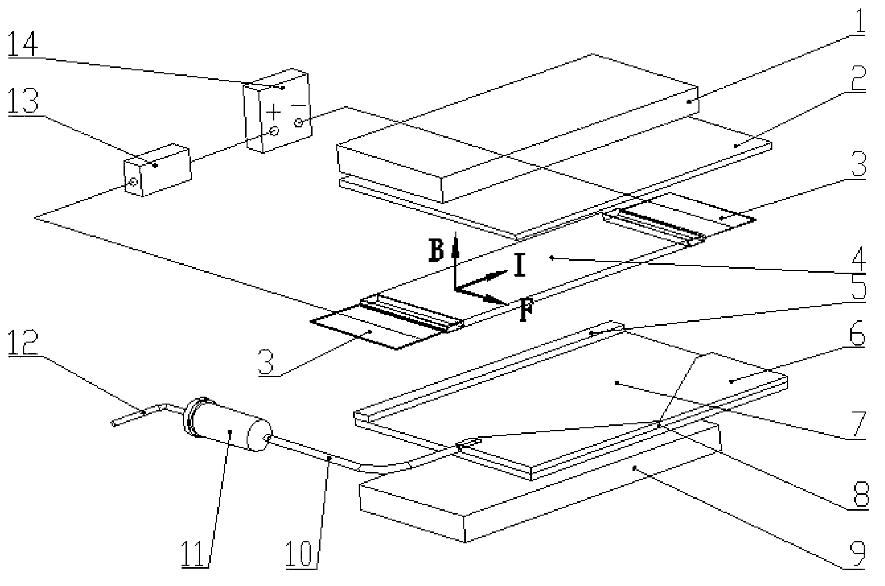
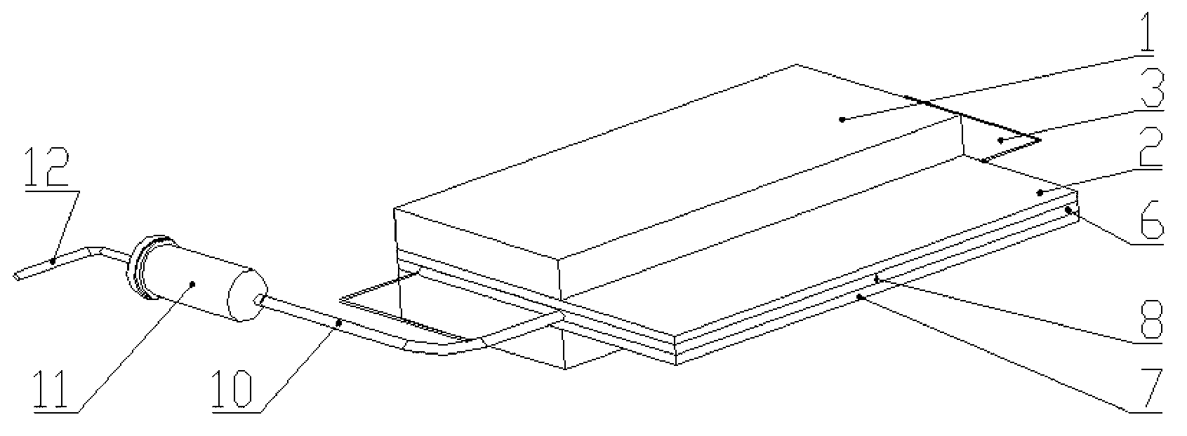
[0015] see figure 1 and 2 , the embodiment of the present invention is provided with upper magnet 1, upper cover plate 2, lower cover plate 7, intermediate baffle plate 5, guide plate 6, lower magnet 9, electrode 3, flexible conductive actuator 4, nozzle 8, infusion fluid Tube 10, liquid storage tank 11, air tube 12, pulse current controller 13 and power supply 14.

[0016] The upper magnet 1 is fixed on the surface of the upper cover plate 2 . The intermediate baffle plate 5 and the guide plate 6 are fixed on the surface of the lower cover plate 7 . The upper cover 2 is connected with the lower cover 7 . The lower magnet 9 is fixed on the bottom surface of the lower cover plate 7 . The electrodes 3 are connected to both ends of the flexible conductive actuator 4 . The flexible conductive actuator 4 is located between the bottom surface of the upper cover plate 2 and the surface of the lower cover plate 7 . The upper cover plate 2 , the lower cover plate 7 , the guide pl...


PUM


Abstract

The invention discloses an ampere force driving micro spraying device, and relates to a micro spraying dispensing device. The ampere force driving micro spraying device is provided with an upper magnet, upper and lower cover plates, an intermediate baffle plate, a guide plate, a lower magnet, an electrode, a flexible electric conducting actuator, a spraying nozzle, a liquid conveying pipe, a liquid storage barrel, a gas pipe, a pulse current controller and a power supply, wherein the upper magnet is fixed on the surface of the upper cover plate; the intermediate baffle plate and the guide plate are fixed on the surface of the lower cover plate; the upper cover plate and the lower cover plate are connected with each other; the lower magnet is fixed on the bottom surface of the lower cover plate; the electrode is connected with the flexible electric conducting actuator which is positioned between the bottom surface of the upper cover plate and the surface of the lower cover plate; the upper cover plate, the lower cover plate, the guide plate and the flexible electric conducting actuator surround to form an injection cavity together; the spraying nozzle is arranged on the guide plate, and is communicated with the outsider; one end of the liquid conveying pipe is communicated with the injection cavity; the other end of the liquid conveying pipe is communicated with the outlet of the liquid storage barrel; the inlet of the liquid storage barrel is connected with one end of the gas pipe; the other end of the gas pipe is externally connected with a pressure gas source; and the power supply is electrically connected with the electrode through the pulse current controller. The ampere force driving micro spraying device is simple in structure, and has a favorable electric control performance.

Description

technical field [0001] The invention belongs to liquid micro-spray technology, relates to a micro-spray dispensing device, in particular to an ampere force-driven micro-spray device. Background technique [0002] Fluid micro-jet dispensing technology has a wide range of applications in liquid crystal displays, mobile phone touch screens, laboratory-on-chip biotechnology, optical microlenses and MEMS devices, especially in VLSI packaging and surface mounting. important role. As the mainstream of future dispensing technology development, non-contact jet dispensing technology is undergoing a transformation from traditional contact dispensing technology. Its market potential is constantly being tapped and its market share continues to expand. [0003] According to different dispensing principles, dispensing technology can be roughly divided into contact type and non-contact type. In recent years, dispensing technology is undergoing a revolution from contact to non-contact. Man...

Claims


Application Information

Patent Timeline
Patent Type & Authority Applications(China)
IPC IPC(8): B05C5/00B05C11/10
Inventor 孙道恒罗志伟王凌云柳娟郑高峰李益盼
Owner XIAMEN UNIV
Learn More