Non-isothermal mold pressing method for glass optical element

An optical element, non-isothermal technology, applied in the field of warm molding, can solve the problems of large temperature change during molding cycle, influence of mold service life and accuracy, etc., to reduce the temperature change range, improve mass production efficiency, and increase economic benefits.

Active Publication Date: 2013-07-24
吴佑林
View PDF5 Cites 9 Cited by
  • Summary
  • Abstract
  • Description
  • Claims
  • Application Information

AI Technical Summary

Problems solved by technology

This method makes the temperature of the mold change greatly during the molding cycle, and t

Method used


Image

  • Non-isothermal mold pressing method for glass optical element
  • Non-isothermal mold pressing method for glass optical element

Examples


Embodiment approach

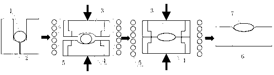
[0022] Such as figure 1 and figure 2 An embodiment of a non-isothermal molding method for glass optical elements of the present invention is shown, and the manufacturing steps include:

[0023] a. Preheating: the glass preform 1 is heated to 150°C-700°C in the preheating tank 2, and the temperature at this time is higher than the transformation temperature Tg of the material and is near the yield temperature At of the material;

[0024] b. Pressurization: Synchronized with preheating, the upper mold 3 and lower mold 4 in the mold are kept at 150°C-700°C under the action of the heating element 5, and the temperature at this time is maintained at 10°C below the transformation temperature Tg of the material degree; put the glass preform 1 with a temperature of 150°C-700°C into the molding cavity formed by the upper mold 3 and the lower mold 4, and use the heating element 5 to heat the glass preform 1, the upper mold 3 and the lower mold 4 Heating to the yield temperature At, ...

Embodiment 1

[0028] For the non-isothermal molding method for infrared chalcogenide glass (type IG6), the manufacturing steps include:

[0029] a. Preheating: glass preform 1 is heated to temperature T in preheating tank 2 1 ,T 1 is 212°C;

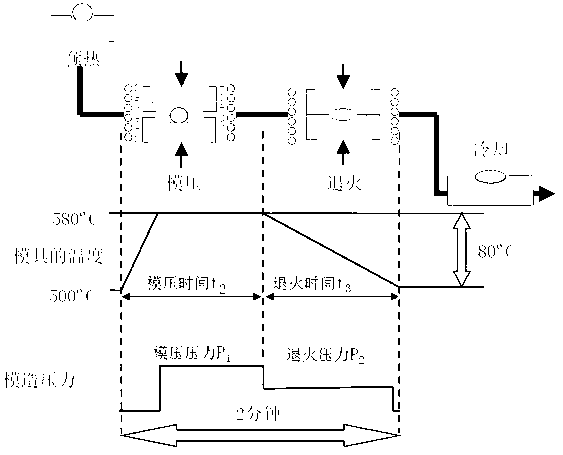
[0030] b. Pressurization: synchronized with preheating, the mold is kept at temperature T 2 , temperature T 2 175°C; put the glass preform 1 with a temperature of 212°C into the molding cavity, heat it to 215°C together, and apply a pressure of 0.5MPa to the upper mold 3 and the lower mold 4, and maintain it for 180s to preform the glass Part 1 is molded into a glass optical element 7;

[0031] c. Annealing: reduce the pressure from 0.5MPa to 0.3MPa and maintain it for 180s, slowly lower the temperature of the mold and glass optical element 7 to 175°C within the same period of time, and annealing will eliminate the internal stress of the glass optical element 7;

[0032] d. Cooling: the annealed glass optical element 7 is taken out from the mold c...

Embodiment 2

[0034] For the non-isothermal molding method for optical glass (type L-BAL35), the manufacturing steps include:

[0035] a. Preheating: glass preform 1 is heated to temperature T in preheating tank 2 1 ,T 1 is 567°C;

[0036] b. Pressurization: synchronized with preheating, the mold is kept at temperature T 2 , temperature T 2 517°C; put the glass preform 1 with a temperature of 567°C into the molding cavity, heat it to 570°C together, and apply a pressure of 0.6MPa to the upper mold 3 and the lower mold 4, and maintain it for 45s to preform the glass Part 1 is molded into a glass optical element 7;

[0037] c. Annealing: reduce the pressure from 0.6MPa to 0.4MPa, and maintain it for 45s, slowly lower the temperature of the mold and glass optical element 7 to 517°C within the same period of time, and annealing will eliminate the internal stress of the glass optical element 7;

[0038] d. Cooling: the annealed glass optical element 7 is taken out from the mold cavity, and ...


PUM


Abstract

The invention discloses a non-isothermal mold pressing method for a glass optical element. According to the method, the steps of glass preformed piece preheating, mold pressing shaping, optical element cooling and the like are performed in parallel in the mold pressing process, and the glass preformed piece preheating temperature and the mold pressing temperature are respectively controlled. The method mainly comprises the steps: preheating, namely heating a glass preformed piece to the temperature T1 in a preheating tank; pressurizing, namely maintaining the mold upper die and the mold lower die to the temperature T2 under the action of the heating device, wherein T1 is more than T2, arranging the preformed piece in a mold pressing cavity, applying pressure to the upper die and the lower die, heating the mold to be T3, maintaining for a certain period of time, and performing die forming on the preformed piece to form an optical element; annealing, namely slowly reducing the temperature of the optical element to be T2 in the mold pressing cavity; and cooling, taking the glass optical element from a die cavity, and cooling the optical element to be room temperature on a cooling plate. The method has the advantages of prolonging the service life of the mold pressing die and improving the batch production efficiency of the glass optical element.

Description

Technical field [0001] The present invention involves a non -equivalent pressure method for the manufacture of glass optical components. Background technique [0002] Generally, the existing optical component manufacturing methods are mostly multi-stage grinding-polishing manufacturing methods, single-point diamond car cutting methods, forming methods for forming formation, and manufacturing methods for molding and forming. [0003] Gourge-polishing manufacturing optical element, this technology uses contact-type friction-polishing methods for optical elements to manufacture, because the grinding marks on the surface of optical elements will make it difficult to improve its quality; secondly, for symmetrical non-spherical lenses, grinding-Doing the method of making difficulties, not only the manufacturing efficiency is low, but also the accuracy is low, and the required optical quality cannot be achieved. Therefore, for non -symmetrical non -spherical lenses and optical component...

Claims


Application Information

Patent Timeline
IPC IPC(8): C03B11/08C03B25/00
CPCY02P40/57
Inventor 周天丰范玉峰
Owner 吴佑林
Why Eureka
Try Eureka