
Automatically-produced light-emitting diode (LED) lamp tube

A technology for LED lamps and lamps, which is applied to parts of lighting devices, semiconductor devices of light-emitting elements, lighting devices, etc., can solve problems such as affecting product quality, low production efficiency, and complicated assembly, and simplify the layout of connecting wires. Effect

Active Publication Date: 2013-07-24
OUTRACE TECH
View PDF4 Cites 7 Cited by
  • Summary
  • Abstract
  • Description
  • Claims
  • Application Information

AI Technical Summary

Problems solved by technology

[0003] A traditional LED lamp usually consists of a lamp body, lamp caps at both ends of the lamp body, and a light-emitting lamp bead circuit board and a power supply circuit board arranged in the lamp body, wherein the circuit board of the light-emitting lamp bead, the power supply circuit board and the lamp cap The connection between them is electrically connected through the connection structure of the connecting lead wires. The assembly of the above-mentioned parts into the lamp body can only be carried out by manual operation. Due to the limitation of manual operation, it has the disadvantages of low production efficiency, high production intensity and affecting product quality.
On this basis, there is a product that is partially mechanically assembled, but the structure of the product is complex and can only be partially assembled. However, due to the limitation of the complex structure of the lamp body assembly parts, the assembly machinery is also particularly complicated. There are limitations of complex processing, complex assembly and high production costs, especially the problem that product quality cannot be guaranteed

Method used


Image

  • Automatically-produced light-emitting diode (LED) lamp tube
  • Automatically-produced light-emitting diode (LED) lamp tube
  • Automatically-produced light-emitting diode (LED) lamp tube

Examples


Embodiment Construction

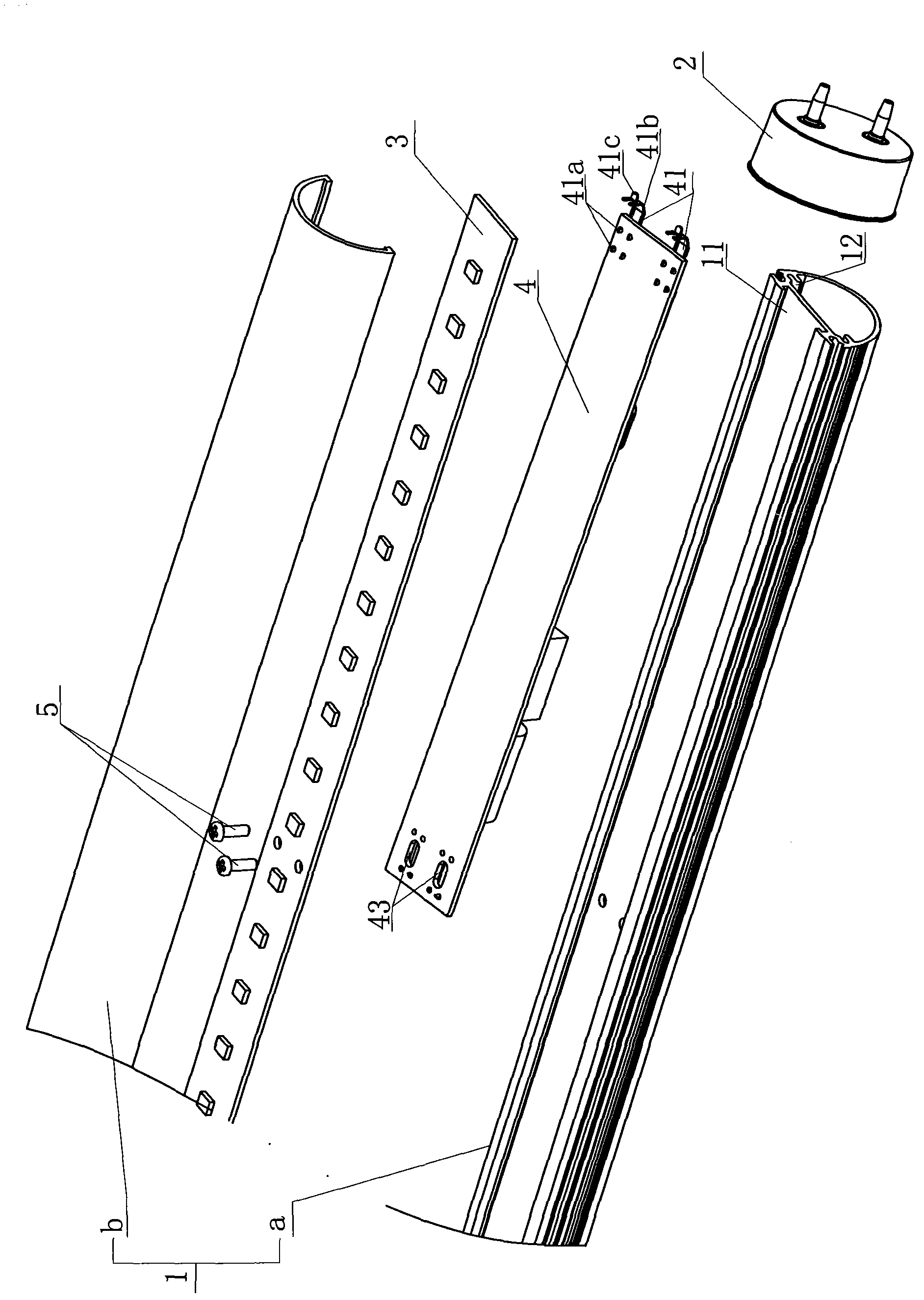
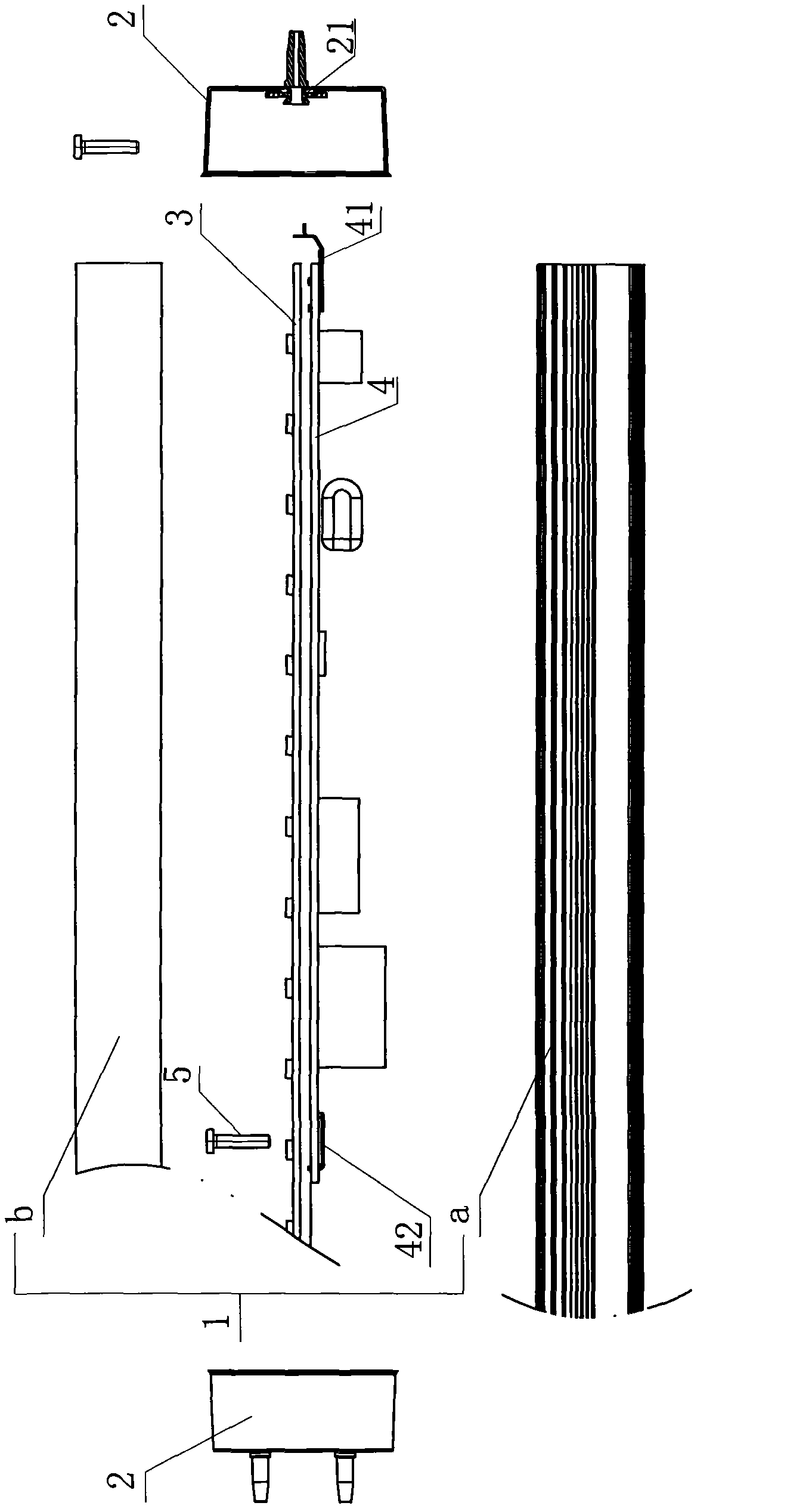
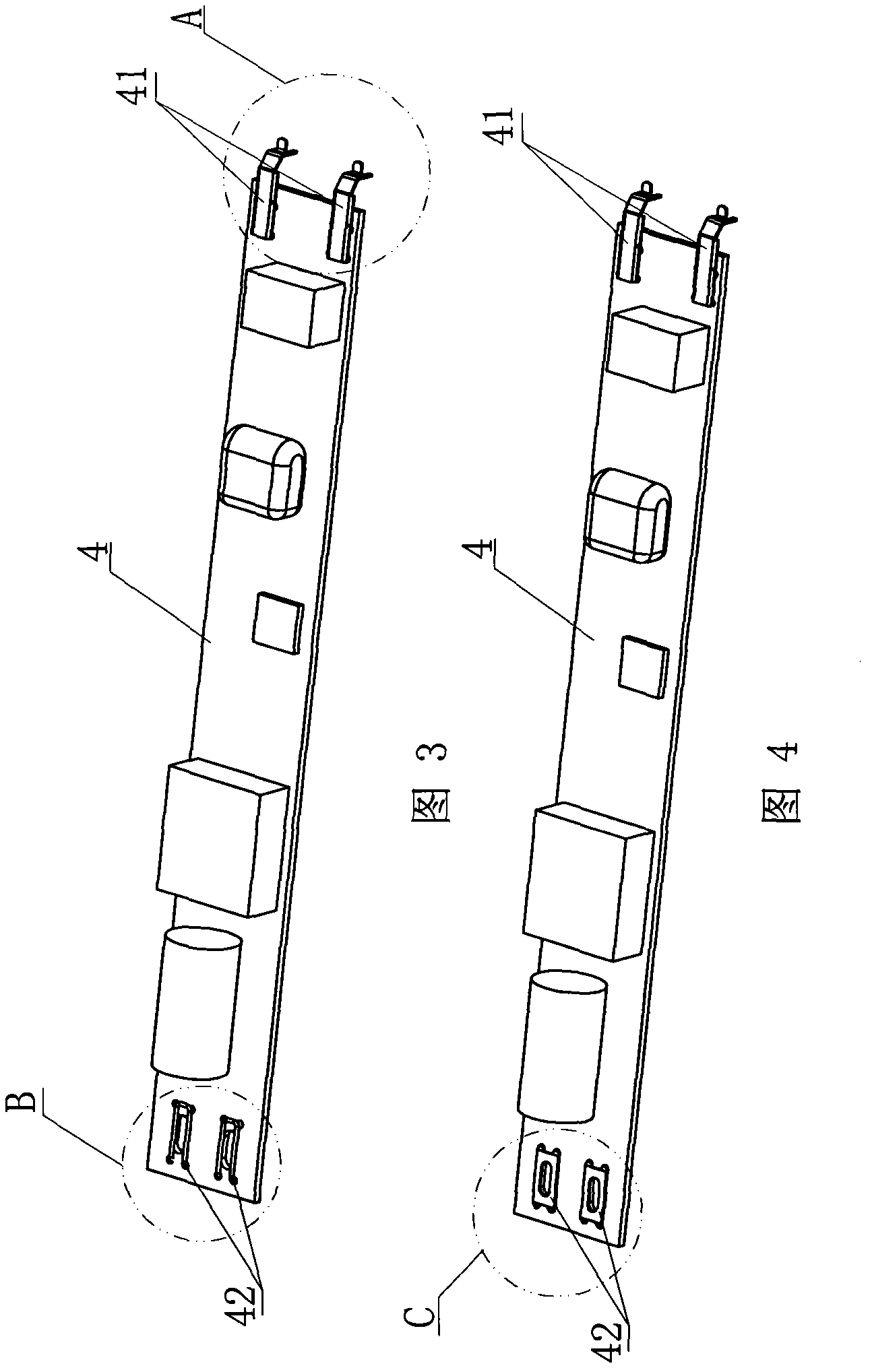
[0042] Such as Figure 1 to Figure 23 Shown: an automatically produced LED lamp tube, including a lamp tube body 1, lamp caps 2 at both ends of the lamp tube body 1, and a light-emitting lamp bead circuit board 3 and a power supply circuit board 4 arranged in the lamp tube body 1, wherein: the lamp The tube body 1 is provided with upper and lower slots 11, 12 arranged in the axial direction, the light-emitting lamp bead circuit board 3 and the power supply circuit board 6 are respectively inserted in it in a stacked arrangement, and one end of the power circuit board 4 is provided with a power supply. Input connector 41, electrical output connector 42 is provided on the board surface, electrode connector 21 is provided at the inner end of the lamp cap 2 to plug and connect with electrical output connector 41, and conductive screw 5 is provided on the board surface of light-emitting lamp bead circuit board 5 for electrical connection Electrical output connector 42 .

[0043] T...


PUM


Abstract

The invention provides an automatically-produced light-emitting diode (LED) lamp tube which comprises a lamp tube body, lamp bases at two ends of the lamp tube body, a luminous bead circuit board and a power circuit board. The luminous bead circuit board and the power circuit board are arranged in the lamp tube body. An upper plug-in groove and a lower plug-in groove are arranged in a substrate in an upper-lower layered mode in the axial direction. The luminous bead circuit board and the power circuit board are respectively arranged in the upper plug-in groove and the lower plug-in groove in an inserted and layered mode. Electrical input connecting pieces are arranged at one end of the power circuit board, and electrical output connecting pieces are arranged at the other end of the power circuit board. Electrode connecting pieces are arranged at the inner end of one lamp base and are connected with the electrical input connecting pieces in a plug-in mode. Conductive screws are arranged on the board surface of the luminous bead circuit board and are electrically connected with the electrical output connecting pieces. The automatically-produced LED lamp tube is simplified in connecting wire distribution, achieves technical effects of stable electricity conduction, and is suitable for automated production of LED ball lamps.

Description

technical field [0001] The invention relates to an LED lamp tube, more specifically, to an automatically produced LED lamp tube. Background technique [0002] With the advancement of electronic technology, the use of LED lighting fixtures is becoming more and more common. LEDs use the luminous properties of semiconductors to emit light. Because LEDs are a green and environmentally friendly light source with long life, low power, and no radiation, they are widely used. Used in backlight, display, traffic lights, urban lighting and other fields. In the future, it will replace incandescent lamps and energy-saving lamps for lighting applications and become a new generation of lighting sources, widely used in indoor and outdoor general lighting and special lighting. [0003] A traditional LED lamp usually consists of a lamp body, lamp caps at both ends of the lamp body, and a light-emitting lamp bead circuit board and a power supply circuit board arranged in the lamp body, where...

Claims


Application Information

Patent Timeline
IPC IPC(8): F21S2/00F21V23/06F21Y101/02F21Y115/10
Inventor 罗嗣辉
Owner OUTRACE TECH
Learn More