A sliding concrete surface flatness test device

A concrete surface and testing device technology, applied in the direction of mechanical roughness/irregularity measurement, etc., to achieve the effect of simple and convenient operation

Active Publication Date: 2015-08-19
HARBIN INST OF TECH
View PDF5 Cites 0 Cited by
  • Summary
  • Abstract
  • Description
  • Claims
  • Application Information

AI Technical Summary

Problems solved by technology

[0004] The purpose of the present invention is to solve the problem that there is no convenient, accurate and fast test device for quantitatively evaluating the smoothness of concrete surface at home and abroad, and to provide a sliding type test device for smoothness of concrete surface

Method used


Image

  • A sliding concrete surface flatness test device
  • A sliding concrete surface flatness test device
  • A sliding concrete surface flatness test device

Examples


specific Embodiment approach 1

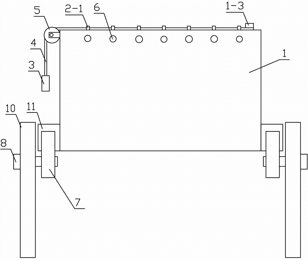
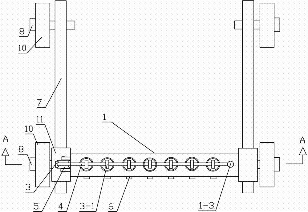
[0013] Specific implementation mode one: combine figure 1 , figure 2 , image 3 , Figure 4 , Figure 5 with Image 6 Describe this embodiment, a sliding concrete surface smoothness testing device described in this embodiment, the device includes a module 1, a counterweight 3, a rigid rope 4, a pulley 5, a plurality of straight rods 2 and a plurality of positioning pins 6. The module 1 is in the shape of a cuboid, and the upper end of the module 1 is provided with a plurality of rod holes 1-1 vertically penetrating the upper and lower ends of the module 1, and the center lines of the plurality of rod holes 1-1 are on the same vertical plane The inner wall of the upper end of the rod hole 1-1 is provided with a through hole through the front and rear sides of the module 1 or one of the sides, and the upper end of the straight rod 2 is fixedly provided with a lifting ring 2-1. The rods 2 are vertical, and the upper side wall of the straight rod 2 is provided with a pin hol...

specific Embodiment approach 2

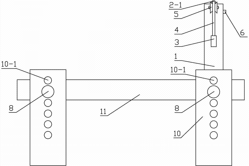
[0014] Specific implementation mode two: combination Figure 5 , Image 6 with Figure 7Describe this embodiment, a sliding concrete surface smoothness testing device described in this embodiment, characterized in that: the device includes a module 1, two counterweights 3, a rigid rope 4, two pulleys 5, a plurality of Straight rod 2 and a plurality of positioning pins 6, the module 1 is a cuboid shape, the upper end of the module 1 is provided with a plurality of rod holes 1-1 that run through the upper and lower ends of the module 1 in the vertical direction, and the plurality of rod holes 1-1 The center line is on the same vertical plane, and the inner wall of the upper end of the rod hole 1-1 has a through hole through the front and rear sides of the module 1 or one of the sides. The through direction of the 1 ring hole is perpendicular to the straight rod 2, and the upper end side wall of the straight rod 2 is provided with a pin hole 2-2, and each rod hole 1-1 is provid...

specific Embodiment approach 3

[0015] Specific implementation mode three: combination figure 1 , image 3 , Figure 4 with Figure 7 To illustrate this embodiment, the upper end of the inner ring of the suspension ring 2-1 in this embodiment is in contact with the rigid rope 4, so that the straight rod 2 will drive the counterweight 3 to move upward through the rigid rope 4 as long as it moves downward. , to make the test more accurate, and the other components and connections are the same as those in the first or second embodiment.


PUM


Abstract

The invention relates to a slide-type concrete surface smoothness test device, belonging to the field of the test of a concrete material, and solving the problem that no device which can be conveniently, accurately and rapidly used for quantitatively evaluating the surface smoothness of the concrete exists both at home and abroad at the present. The upper end of a box body is provided with a plurality of rod holes, wherein the inner wall of each rod hole is provided with a through hole running through the side surfaces of the box body, the upper end of each straight rod is provided with a suspension ring, the side wall of each straight rod is provided with a pin shaft hole, the straight rods are respectively arranged in the rod holes, a positioning pin is sequentially arranged inside the through hole and the pin shaft hole on the straight rod in a penetrating way, the left side of the box body is provided with a pulley, the right side of the upper end of the box body is provided with a rope pole, one end of a rigid rope is fixed on the rope pole, the other end of the rigid rope is fixedly provided with a balancing weight, the weight of the balancing weight is smaller than half of the weight of each straight rod, the rigid rope is sequentially arranged in the suspension rings in a penetrating way, and a fixed point at the right end of the rigid rope, the central line of the rod holes and the center of the pulley are on a same vertical plane. The slide-type concrete surface smoothness test device is used for evaluating the surface smoothness of the concrete.

Description

technical field [0001] The invention relates to a concrete surface testing device, which belongs to the field of concrete material testing. Background technique [0002] As a new type of rapid mechanical construction method for modern concrete engineering structures, slipform construction is widely used in many construction engineering fields such as highways and airport pavements. Since the dry hard concrete used in the traditional sliding form construction technology can only be fully compacted under intensive external vibration conditions, the actual project is often destroyed prematurely due to the over-vibration of the concrete in the local area around the vibrator. In response to this specific technical problem, in recent years, it has been proposed at home and abroad to apply modified self-compacting concrete to slipform construction without vibrating forming. Since high fluidity is required to achieve the effect of vibration-free self-compacting, and high cohesion i...

Claims


Application Information

Patent Timeline
Patent Type & Authority Patents(China)
IPC IPC(8): G01B5/28
Inventor 高小建姜山罗忠涛
Owner HARBIN INST OF TECH
Why Eureka
Try Eureka