Full-automatic SMT net plate thickness measuring method

A thickness measurement, fully automatic technology, applied in the direction of measuring devices, instruments, optical devices, etc., can solve the problem of measuring the thickness of the stencil single, unable to express the thickness of a specific area, etc., to reduce errors, improve efficiency, and improve accuracy Effect

Inactive Publication Date: 2013-07-24
KUNSHAN THETA MICRO
View PDF4 Cites 3 Cited by
  • Summary
  • Abstract
  • Description
  • Claims
  • Application Information

AI Technical Summary

Problems solved by technology

[0006] The technical problem to be solved by the present invention is the problem that the measurement of the thickness of the stencil is single and cannot represent the thickness of a specific area in the prior art

Method used


Image

  • Full-automatic SMT net plate thickness measuring method
  • Full-automatic SMT net plate thickness measuring method
  • Full-automatic SMT net plate thickness measuring method

Examples


Embodiment 1

[0024] A method for measuring the thickness of a fully automatic SMT stencil, comprising the following steps:

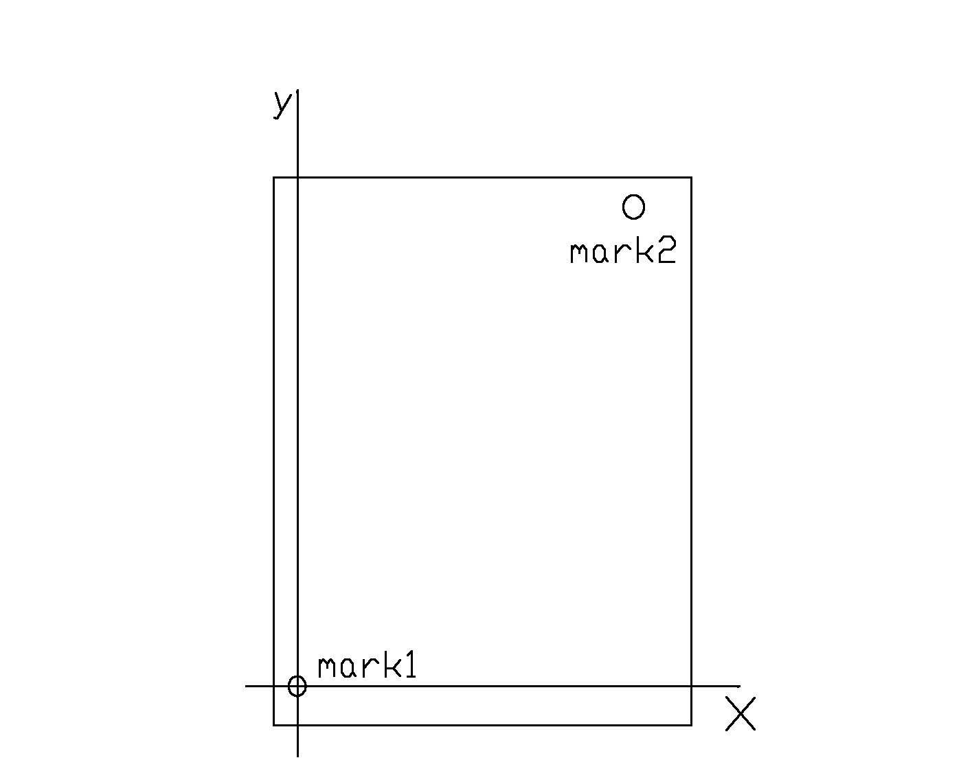
[0025] a) Use laser cutting to make two Mark points at both ends of a diagonal line of the SMT screen, and establish a coordinate system according to their actual positions. The coordinates of Mark1 point are (0,0), and the coordinates of Mark2 point Count as (x,y);

[0026] b) Put the stencil on the thickness measuring workbench, which is equipped with double vertical laser displacement sensors and cameras;

[0027] c) For measurement, first move the camera to the vicinity of the Mark point for automatic identification, record the actual machine coordinates (x1, y1) of the Mark1 point, then move to the second Mark point, and record the machine coordinates (x2, y1) y2);

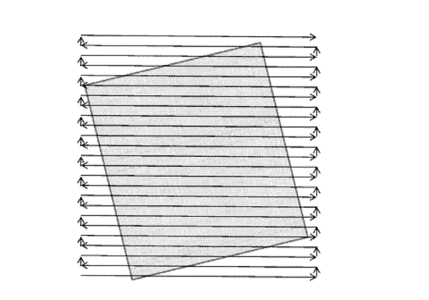
[0028] d) Carry out automatic scanning, and calculate the thickness of the upper plate on the path according to the data obtained by the laser displacement sensor during the scanning process;

[...

Embodiment 2

[0032] This method adopts methods such as making Mark points, automatically identifying Mark points, and alignment to generate thickness map information corresponding to the stencil. First of all, it is necessary to use laser cutting to make two Mark points at both ends of a diagonal line of the SMT stencil and establish a coordinate system according to their actual positions, such as figure 2 As shown, the coordinates of the Mark1 point are (0,0), and the coordinates of the Mark2 point are (x,y).

[0033] Put the stencil on the thickness measurement workbench, which is equipped with a double vertical laser displacement sensor and a camera. When starting the measurement, first move the camera to the vicinity of the Mark point for automatic identification and record the position of the Mark1 point on the actual machine coordinates (x1, y1), then move to the second Mark point, and also record the machine coordinates (x2, y2).

[0034] Then start automatic scanning. During the ...

Embodiment 3

[0039] A fully automatic SMT stencil thickness measurement method, including the following steps: a) Use laser cutting to make two Mark points at both ends of a diagonal line of the SMT stencil, and establish a coordinate system based on their actual positions , the coordinates of Mark1 point are (0,0), and the coordinates of Mark2 point are (x,y); b) Put the stencil on the thickness measuring table, which is equipped with double vertical laser displacement sensors and the camera; c) to measure, first move the camera to the vicinity of the Mark point for automatic identification, record the actual machine coordinates (x1, y1) of the Mark1 point, then move to the second Mark point, and record the machine coordinates as well (x2, y2); d) Carry out automatic scanning, calculate the thickness of the upper plate on the path according to the data obtained by the laser displacement sensor during the scanning process; e) perform alignment operation according to the obtained virtual coo...


PUM


Abstract

The invention relates to a full-automatic SMT net plate thickness measuring method which mainly resolves the problems that in existing full-automatic SMT net plate thickness measuring technology, measuring data cannot be stored and reused, and net plates cannot be combined into a whole. The full-automatic SMT net plate thickness measuring method is adopted and includes the steps: two Mark points are manufactured at two ends of a diagonal line of an SMT net plate in a laser cutting mode, and a coordinate system is established; placing the net plates on a double-vertical-type laser displacement sensor and a thickness measuring platform of a camera; measurement is conducted, a position actual machine platform coordinate (x1, y1) of a Mark 1 point is recorded, and at the same time, a machine platform coordinate (x2, y2) is recorded; automatic scanning is conducted, data are obtained according to the laser displacement sensors during the process of scanning, and thicknesses of the net plates on a patch are computed; and the technical scheme of a thickness chart, an upper surface arc face chart, and a lower surface arc face chart is generated. The problems are well resolved, and the full-automatic SMT net plate thickness measuring method can be applied to laser micro-processing industries.

Description

[0001] technical field [0002] The invention relates to a method for measuring the thickness of a fully automatic SMT stencil, in particular to a method for measuring thickness and flatness using a laser displacement sensor in the laser microprocessing industry. Background technique [0003] [0004] In the laser micromachining industry, for SMT (Surface Mount Technology) stencils, it is necessary to measure the thickness of the stencil to check whether the stencil meets the requirements. A point or a certain area thickness and marked on the screen. However, this method has no alignment function. If the stencil is removed and the thickness information of other areas is needed during reprocessing, the stencil must be placed on a thickness gauge to measure again, which increases repetitive work and reduces production efficiency. Such as figure 1 As shown, the stencil is misplaced, the scanning direction is inconsistent with the stencil direction, and the data obtained by s...

Claims


Application Information

Patent Timeline
Patent Type & Authority Applications(China)
IPC IPC(8): G01B11/06
Inventor 魏志凌宁军沈晓
Owner KUNSHAN THETA MICRO
Why Eureka
Try Eureka