
Detection device for continuously welded rails

A technology of seamless line rails and detection devices, which is applied in the direction of using sound waves/ultrasonic waves/infrasonic waves to analyze solids, etc. It can solve problems such as large limitations, no online detection of broken rails and stress, and subsequent rupture of optical fibers, etc., to achieve security The effect of safe operation

Active Publication Date: 2013-07-24
BEIJING JIAOTONG UNIV
View PDF10 Cites 16 Cited by
  • Summary
  • Abstract
  • Description
  • Claims
  • Application Information

AI Technical Summary

Problems solved by technology

The real-time detection method of optical fiber rail breakage is to use a standard single-mode optical fiber attached to the rail by epoxy resin tape for detection; one end of the optical fiber is connected to the light source, and the other end is the receiver. If the rail breaks, the optical fiber will be broken accordingly, and the light It will not be able to reach the receiver, so it can be judged that a broken track has occurred; but this method is only suitable for short track detection and has great limitations
The stress real-time rail breaking detection method uses some stress measurement sensors, which are installed on the rail waist at certain distances. By using corresponding analysis techniques, the stress and temperature changes detected by the sensors are calculated and compared. Some combinations of pressure and temperature It can indicate broken track, track deformation, or both; but the performance index of this method is poor, and the research and development value is not high
[0007] 2) The existing rail stress detection technology usually uses the critical angle refraction method to measure the material stress. The measurement results reflect the stress changes in the path of ultrasonic propagation below the material surface, and cannot reflect the average stress inside the entire material.
[0008] Moreover, the existing technology does not have a method for online detection of rail breakage and stress at the same time

Method used


Image

  • Detection device for continuously welded rails
  • Detection device for continuously welded rails
  • Detection device for continuously welded rails

Examples


Embodiment 1

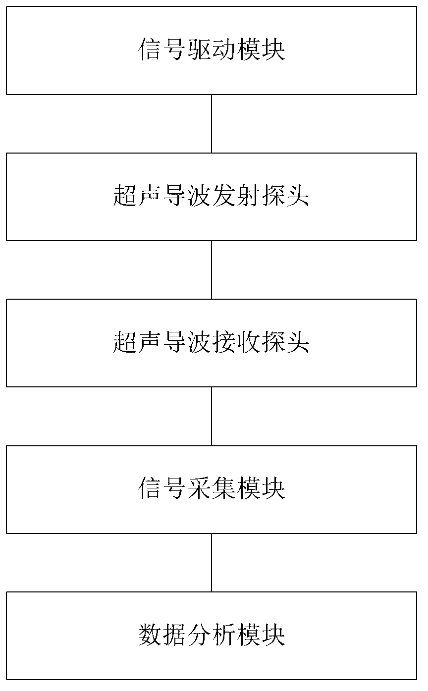
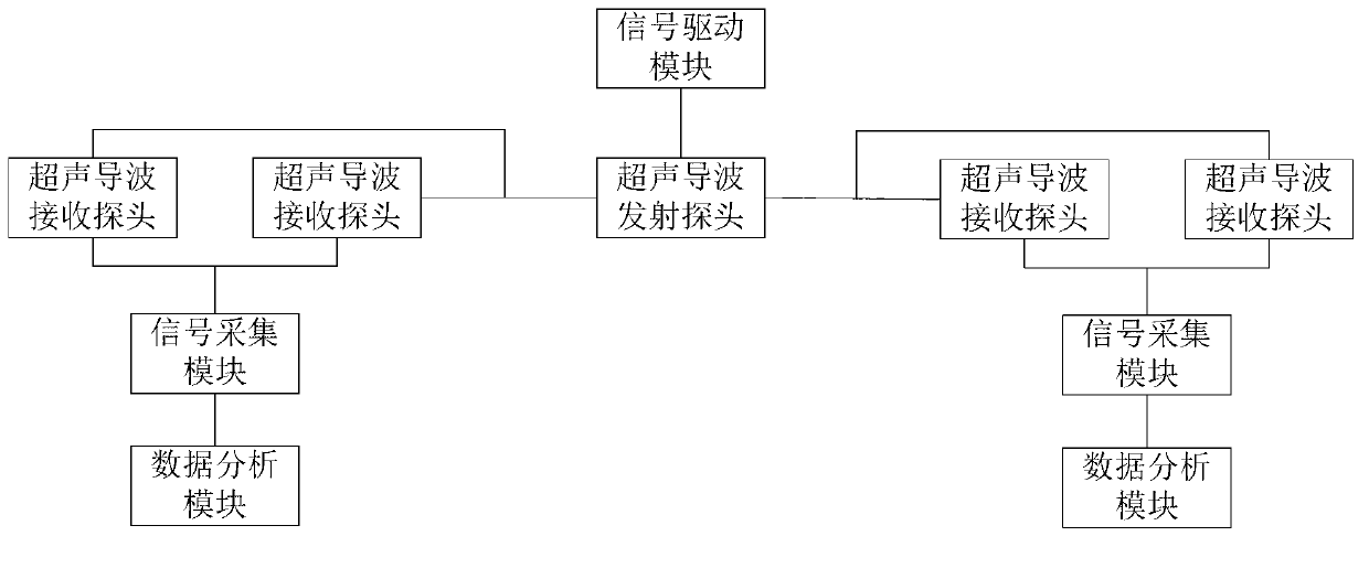
[0022] figure 1 A detection device for a seamless track rail provided in an embodiment of the present invention, the device mainly includes:

[0023] Ultrasonic guided wave transmitting probe, ultrasonic guided wave receiving probe, data analysis module;

[0024] A group of ultrasonic guided wave receiving probes are respectively provided on the front and rear sides of the ultrasonic guided wave transmitting probe; wherein each group of ultrasonic guided wave receiving probes includes two ultrasonic guided wave receiving probes arranged along the rail direction, according to the two The sequence of signals received by the ultrasonic guided wave receiving probes arranged along the rail direction determines the detected line;


PUM


Abstract

The invention discloses a detection device for continuously welded rails. The device comprises: an ultrasonic guided wave transmitting probe, ultrasonic guided wave receiving probes and a data analysis module. The front side and back side of the ultrasonic guided wave transmitting probe are respectively provided with a set of ultrasonic guided wave receiving probes, and each set of ultrasonic guided wave receiving probes includes two ultrasonic guided wave receiving probes arranged along the rail direction, and the detected circuit is determined according to the signal receiving sequence of the two ultrasonic guided wave receiving probes arranged along the rail direction. The output ends of each set of ultrasonic guided wave receiving probes are connected to the data analysis module, which is used for stress and rail breakpoint detection according to the ultrasonic guided wave signals received by the ultrasonic guided wave receiving probes. With the device disclosed in the invention, the detection accuracy and efficiency are improved, and the driving safety is ensured.

Description

technical field [0001] The invention relates to the field of rail detection, in particular to a detection device for seamless line rails. Background technique [0002] With the rapid development of high-speed railways, seamless lines have been widely promoted and applied all over the world. The seamless line eliminates the rail joints to a certain extent, reduces train vibration and noise, makes the train run smoothly, and prolongs the service life of line equipment and rolling stock. However, with the disappearance of rail joints, due to the effects of rail joint resistance and ballast bed longitudinal resistance, dozens or even more rails welded together cannot freely expand and contract when the rail temperature changes, so longitudinal temperature stress will be generated in the rails. The temperature of the long rail changes by 1°C relative to the locked rail temperature, and the longitudinal stress in the rail fixing area changes by 2.43MPa (megapascals). If the rail ...

Claims


Application Information

Patent Timeline
IPC IPC(8): G01N29/04
Inventor 余祖俊许西宁朱力强史红梅郭保青
Owner BEIJING JIAOTONG UNIV
Learn More