Device and method for joining workpieces by means of a laser beam and movable pressing element

A laser beam and laser welding technology, applied in auxiliary devices, laser welding equipment, transportation and packaging, etc., can solve problems such as unbearable acceleration, feed speed limitation, and not involving the shape or structure of the workpiece to be processed

Inactive Publication Date: 2013-07-24
SCANSONIC MI
View PDF7 Cites 11 Cited by
  • Summary
  • Abstract
  • Description
  • Claims
  • Application Information

AI Technical Summary

Problems solved by technology

[0005] However, the above-mentioned linear guidance scheme can only produce a straight beam guidance. In order to produce a curved weld, it is necessary to reposition the workpiece to be welded, which is very time-consuming
Furthermore, the linear drive provides a given feed rate for the laser process, which is limited, for example, by the mechanical stability of the collimator system, which usually has sensitive optical components, so that Difficult to withstand excessive acceleration
[0006] In addition, EP2149421A1 does not refer to the shape or structure of the workpiece to be processed; for example, the device and the corresponding pressure element provided in this case do not take into account the following situations: the shape of the workpiece to be fixed may vary and / or irregular shapes may need to be processed ( For example, workpieces that are not plane-parallel but are slightly three-dimensionally arched or three-dimensionally stepped)
When machining such irregularly shaped workpieces, the following situation may arise: the exit slot of the housing may not be completely covered by the workpiece, at which point the laser radiation may bypass the workpiece and exit the housing and strike personnel

Method used


Image

  • Device and method for joining workpieces by means of a laser beam and movable pressing element
  • Device and method for joining workpieces by means of a laser beam and movable pressing element
  • Device and method for joining workpieces by means of a laser beam and movable pressing element

Examples


Embodiment Construction

[0085] With the help of Figures 1 to 9 The illustrated embodiments illustrate the invention, wherein identical or similar features are indicated by the same reference symbols.

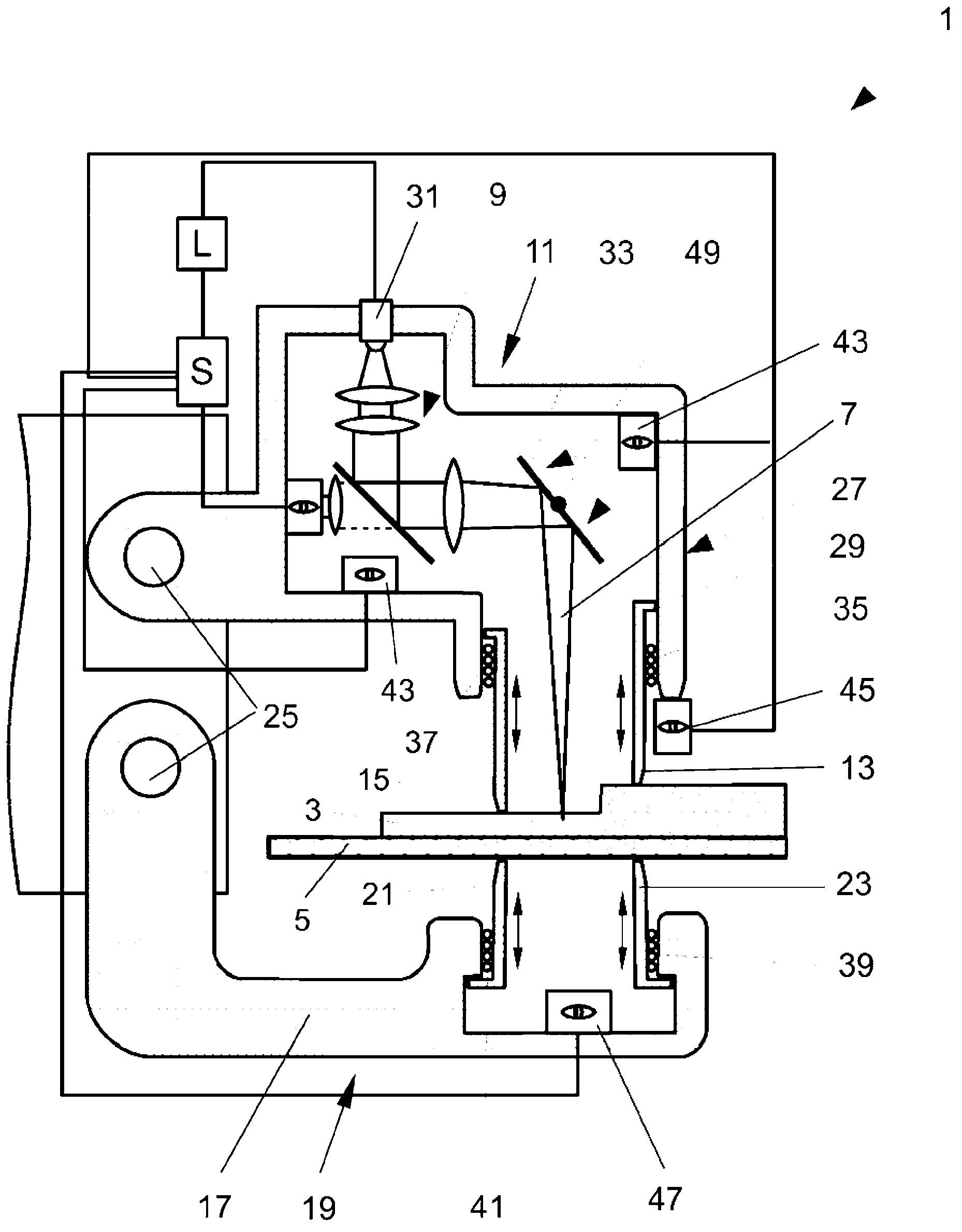
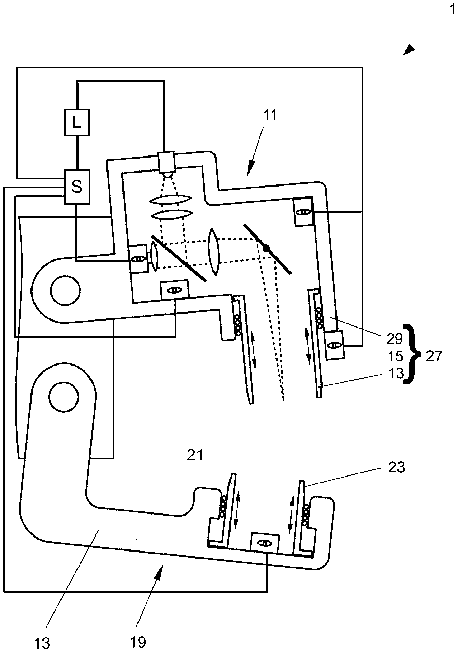
[0086] figure 1In one embodiment of the invention, a laser welding device 1 embodied as a welding torch 1 is joining two workpieces 3 , 5 by means of a laser beam 7 , wherein the laser beam 7 is guided and positioned by means of an optical scanner 9 . The welding torch 1 has two upper pressure elements 13 , 15 arranged on the upper arm 11 of the welding torch 1 , and two lower pressure elements 21 , 23 arranged on the bracket 17 of the lower arm 19 of the welding torch 1 . The arms 11 , 19 are rotatably connected to the guide unit 25 and press the workpieces 3 , 5 to be joined—here the metal plates 3 , 5 —together by means of the pressing elements 13 , 15 , 21 , 23 . The upper arm 11 forms a housing 27 which encloses the optical scanner 9 and the laser beam 7 extending from the optical scanner 9 to ...


PUM


Abstract

The invention relates to a method and a device (1) for joining workpieces (3, 5) by means of a laser beam (7), the device (1) comprising: a scanning optical system (9) for guiding the laser beam (7); a pressing element (13, 15, 21, 33), which is pressed onto at least one of the workpieces (3, 5) in a pressing direction in order to fix the workpieces (3, 5) during the joining process; and a housing (11), which encloses the scanning optical system (9) and the laser beam (7) extending from the scanning optical system (9) to the workpieces (3, 5). The pressing element (13, 15, 21, 23) forms part of the housing (11) and is movable relative to the remainder of the housing (11) with at least one degree of freedom.

Description

technical field [0001] The invention relates to a laser welding device and a corresponding method for joining workpieces by means of a laser beam. Background technique [0002] The laser beam welding process is especially used where high welding speeds, narrow weld seams and workpieces with low thermal deformation need to be joined. For example, the workpieces to be joined are fixed in the desired position with the help of special mounting and fixing devices, and then connected by laser beam welding. [0003] The light intensity of laser welding is high, so the laser welding device is usually operated in a separate safety chamber to avoid the impact of laser radiation on the environment. Such a safe chamber generally encloses the entire laser processing device, which increases the volume of the device and increases the difficulty and cost of the operation of the chamber. [0004] EP 2149421 A1 describes a device for welding workpieces by means of a laser beam, in which the...

Claims


Application Information

Patent Timeline
Patent Type & Authority Applications(China)
IPC IPC(8): B23K26/02B23K26/03B23K26/22B23K26/24B23K37/04B23K26/08B23K26/14
CPCB23K26/0807B23K2201/006B23K2201/18B23K37/0443B23K26/023B23K26/1464B23K26/041B23K26/032B23K26/22B23K26/034B23K26/03B23K26/24B23K26/037B23K26/082B23K26/042B23K26/70B23K2101/006B23K2101/18B23K26/0821B23K26/21B23K26/02B23K26/04B23K26/08B23K37/04B23Q27/00
Inventor 伊戈尔·哈舒克阿维德·基里安
Owner SCANSONIC MI
Why Eureka
Try Eureka