Rotation angle detection device
A technology of rotation angle detection and rotation angle, which is applied in the direction of measuring device, using electric device, using electric/magnetic device to transmit sensing components, etc., to achieve the effect of equal magnetic collection effect, uniform spatial distribution, and improved removal accuracy.
- Summary
- Abstract
- Description
- Claims
- Application Information
AI Technical Summary
Problems solved by technology
Method used
Image

Examples
Embodiment approach 1
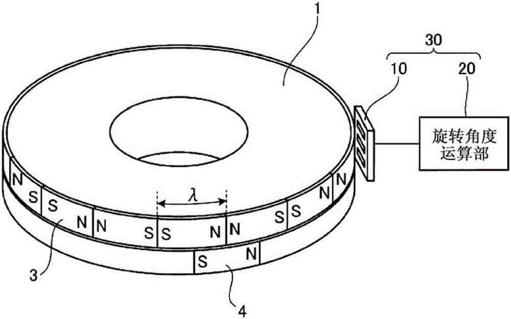
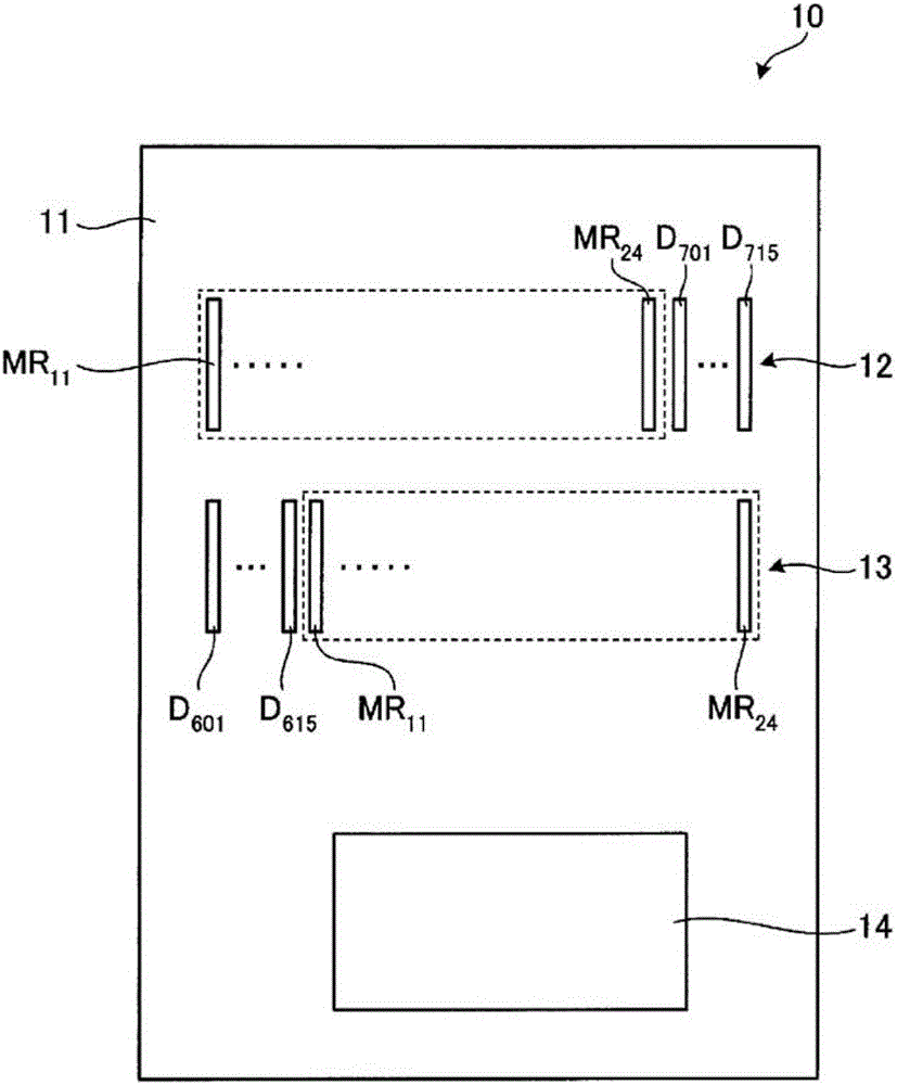
[0024] use figure 1 and figure 2 , the rotation angle detection device 30 according to Embodiment 1 will be described. figure 1 It is a diagram showing a schematic configuration of the rotation angle detection device 30 according to the first embodiment. figure 2 It is a figure which shows the structure of the magnetic sensor 10 in Embodiment 1.
[0025] Rotation angle detecting device 30 such as figure 1 As shown, the rotation angle of the rotary drum 1 is detected. The rotary drum 1 has a multipole magnetic pattern 3 and a magnetic pattern 4 on its outer periphery, respectively. In the multi-pole magnetic pattern 3 , N poles and S poles are formed by alternately repeating magnetization at a magnetization pitch λ. The magnetic pattern 4 is magnetized at one position and is used to indicate the origin of the rotary drum 1 in the circumferential direction.
[0026] The rotation angle detection device 30 has a magnetic sensor 10 and a rotation angle calculation unit 20 ....
Embodiment approach 2
[0110] Next, the rotation angle detection device 30i according to Embodiment 2 will be described. Hereinafter, description will be given centering on parts different from Embodiment 1. FIG.
[0111] Rotation angle detection device 30i is different from Embodiment 1 in the configuration within the common pattern of A-phase detection track 12i and B-phase detection track 13i. That is, if Figure 5 As shown, the common pattern also has a dummy device group D3i and a dummy device group D4i. Figure 5 It is a figure which shows the structure in the common pattern of A phase detection track 12i and B phase detection track 13i.
[0112] The dummy element group D3i is arranged on both outer sides of the detection element group MR1. The dummy element group D3i has a plurality of dummy magnetoresistive elements (plurality of third dummy magnetoresistive elements) D31i, D32i. The respective dummy magnetoresistive elements D31i and D32i have the same shape and size as the respective m...
Embodiment approach 3
[0125] Next, a rotation angle detection device 30j according to Embodiment 3 will be described. Hereinafter, description will be given centering on parts different from Embodiment 1. FIG.
[0126] Rotation angle detection device 30j is different from Embodiment 1 in the configuration within the common pattern of A-phase detection track 12j and B-phase detection track 13j. That is, if Figure 6 As shown, the common pattern also has a dummy element group D5j. Figure 6 It is a figure which shows the structure in the common pattern of A phase detection track 12j and B phase detection track 13j.
[0127] The dummy element group D5j is arranged between the detection element group MR1 and the detection element group MR2. The dummy element group D5j has a plurality of dummy magnetoresistive elements (plurality of fourth dummy magnetoresistive elements) D51j to D55j. The dummy magnetoresistive elements D51j to D55j have the same shape and size as the magnetoresistive elements MR11...
PUM
 Abstract
Description
Claims
Application Information
 - R&D
- Intellectual Property
- Life Sciences
- Materials
- Tech Scout
- Unparalleled Data Quality
- Higher Quality Content
- 60% Fewer Hallucinations
Browse by: Latest US Patents, China's latest patents, Technical Efficacy Thesaurus, Application Domain, Technology Topic, Popular Technical Reports.
© 2025 PatSnap. All rights reserved.Legal|Privacy policy|Modern Slavery Act Transparency Statement|Sitemap|About US| Contact US: help@patsnap.com