Conveying robot

A technology for handling robots and workpieces, applied in the field of handling robots, to achieve the effect of reducing adverse effects

Inactive Publication Date: 2013-07-31
YASKAWA DENKI KK
View PDF8 Cites 11 Cited by
  • Summary
  • Abstract
  • Description
  • Claims
  • Application Information

AI Technical Summary

Problems solved by technology

[0006] However, in a conventional transfer robot including a plurality of holding units, in some cases another holding unit is disadvantageously subjected to radiant heat radiated from a holding unit during transfer of a high-temperature substrate or radiant heat radiated from a heated substrate during transfer Impact

Method used


Image

  • Conveying robot
  • Conveying robot
  • Conveying robot

Examples


no. 1 approach )

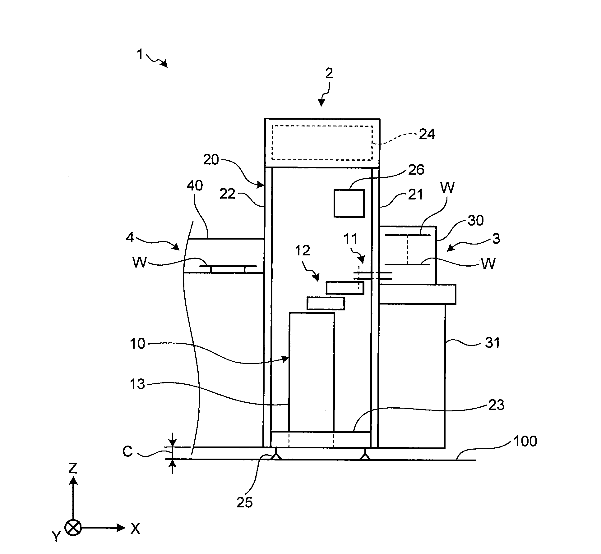
[0024] First, refer to figure 1 The overall configuration of the transport system according to the first embodiment will be explained. figure 1 It is a schematic diagram showing the overall configuration of the conveying system 1 according to the first embodiment.

[0025] For ease of understanding, in figure 1 , A three-dimensional Cartesian coordinate system is shown, the three-dimensional Cartesian coordinate system including a Z axis in which the positive direction is vertically upward and the negative direction is vertically downward (ie, the "vertical direction"). Therefore, the direction along the XY plane means "horizontal direction". In some cases, the Cartesian coordinate system is shown in other drawings used in the following description. In addition, in the following, for a component including a plurality of elements, only one of the elements is denoted with a reference numeral, and the reference numerals of other elements are omitted in some cases.

[0026] Such as fi...

no. 2 approach )

[0092] Next, the transfer robot 10c according to the second embodiment will be explained. Picture 9 with Picture 10 It is a schematic plan view of the transfer robot 10c according to the second embodiment. Such as Picture 9 As shown, the transport robot 10c includes a trunk part 5, and a left arm unit 5a and a right arm unit 5b extending from the trunk part 5.

[0093] The trunk part 5 is a basic unit of a transport robot 10c fixed to the floor or the like, and is formed so that the top surface on the positive side of the Y axis (hereinafter referred to as "right side") is in the Z axis direction than the negative direction of the Y axis The top surface of the side (hereinafter referred to as "left side") is higher.

[0094] The left arm unit 5a includes a first arm 51a and a second arm 52a. The first arm 51a has the base end side provided on the top surface of the left side of the trunk portion 5 so as to be rotatable about an axis z1 that is a rotation axis parallel to the Z...


PUM


Abstract

A robot system according to an aspect of the embodiments includes a plurality of work holding units and a heat insulating member. The work holding units each hold a work to be conveyed on one surface and are arranged vertically one over another in some cases during conveying of the work. The heat insulating member is provided on another surface side of at least one of the work holding units.

Description

Technical field [0001] The embodiments discussed herein involve handling robots. Background technique [0002] Conventionally, there is known a transfer robot that transfers substrates (for example, wafers) into or out of processing facilities in a space formed in a local cleaning device called EFEM (Front End Equipment Module) during semiconductor manufacturing. [0003] A transfer robot that transfers a substrate generally includes an arm provided with a holding unit that holds the substrate at its end and holds the substrate (for example, placing the substrate on the upper surface of the holding unit) while operating in a horizontal direction The arm and the holding unit carry the substrate. [0004] Examples of such a transfer robot include a transfer robot that includes a plurality of holding units and transfers a plurality of parallel substrates onto planes parallel to each other by individually operating the holding units (for example, see Japanese Patent Laid-Open Publicatio...

Claims


Application Information

Patent Timeline
Patent Type & Authority Applications(China)
IPC IPC(8): B25J11/00H01L21/677
CPCH01L21/67742H01L21/677H01L21/68707B25J11/0095B25J11/00B25J9/042Y10S414/141Y10S901/49
Inventor 安藤隆治日野一纪古谷彰浩
Owner YASKAWA DENKI KK
Why Eureka
Try Eureka