Dam face system of hydraulic moving dam

A technology for movable dams and dam surfaces, which is applied in water conservancy projects, sea area projects, coastline protection, etc. It can solve the problems of high maintenance costs, increased costs, and high maintenance costs, so as to improve the service life and use effect, and increase the carrying capacity , the effect of improving the stress situation

Inactive Publication Date: 2013-07-31
SUZHOU ZHENGXINTAI AUTOMATION SYST
View PDF5 Cites 6 Cited by
  • Summary
  • Abstract
  • Description
  • Claims
  • Application Information

AI Technical Summary

Problems solved by technology

[0002] The main applications in water conservancy systems include ram dams, rubber dams, water conservancy automatic flip dams and hydraulic lifting dams. Because ram dams are made of steel, the cost of starting equipment is large and the maintenance costs are high; rubber dams are the first in the United States. The mature technology has the advantages of low production cost and convenient maintenance in the later stage, but it has the problems of easy damage, low lifting efficiency and short life; the hydraulic automatic flap dam, as an advanced technology in Japan, also has the advantages of convenient maintenance in the later stage, but When applied to complex river systems, it is easy to be stuck by sand, stones, trees, bamboo and other silts in the river, so that the dam surface cannot be completely closed, and it must be cleaned manually, which is inconvenient to use; the hydraulic dam solves the above shortcomings and is easy to use , suitable for water conservancy construction of any complex river course, but if the dam surface adopts a steel structure, it will inevitably cause problems such as increased costs and high maintenance costs in the later period. For this reason, it is considered to replace the dam surface with a steel structure and sufficient compressive strength

Method used


Image

  • Dam face system of hydraulic moving dam
  • Dam face system of hydraulic moving dam
  • Dam face system of hydraulic moving dam

Examples


Embodiment Construction

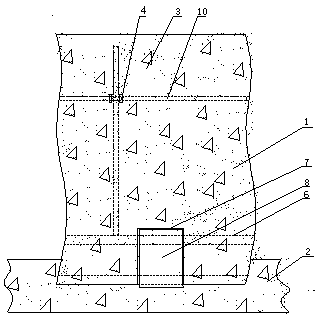
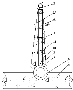
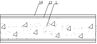
[0019] figure 1 and figure 2 The hydraulic movable dam surface system includes dam surface 1, horizontal foundation 2, dam surface back surface 3, earring structure 4, steel bar grid 5, seamless steel pipe 6, gap 7, rotating sleeve coaxial 8, steel pipe 9, Cross hidden beams 10, connecting ribs 11, dam surface facing water 12, environmental protection polymer chemical coating 13, text layer or pattern layer 14.

[0020] The hydraulic movable dam surface system of the present invention is mainly composed of several steel concrete structure dam surfaces 1 spliced ​​along a straight line, and is cast around the seamless steel pipe 6 arranged at the bottom of the dam surface 1 along the extending direction of the dam surface, and is directly fixed around the dam surface. The rotating sleeve on the horizontal foundation 2 rotates coaxially 8, thereby realizing the relative rotation between the dam surface 1 and the horizontal foundation 2. In order to ensure the connection stren...


PUM


Abstract

The invention discloses a dam face system of a hydraulic moving dam. The dam face system of the hydraulic moving dam mainly comprises a plurality of dam faces spliced along a straight line, wherein each dam face is movably connected with a horizontal base. The dam face system is characterized in that each dam face adopts a reinforced concrete structure; steel grids in consistency with the front structure of the reinforced concrete structure are formed in the reinforced concrete structure; a seamless steel pipe arranged on the bottom edge of each dam face is directly poured at the bottom of the reinforced concrete structure; a plurality of gaps are formed at the bottom of the reinforced concrete structure, and are facing against the position of a rotation quill shaft mounted on the horizontal base; and the central axis of the rotation quill shaft coincides with the central axis of the seamless steel pipe. As the reinforced concrete structure equipped with steel grids structure is used for the dam face to use, the manufacture cost is low, the structure is simple, and the bearing strength is high; moreover, hidden beams interlacing with one another in a cross manner can be arranged at the stress position of the dam face, so that the stress condition of the dam face can be improved, the service life of the dam face is prolonged, and the use effect of the dam face can be improved.

Description

technical field [0001] The invention relates to a hydraulic movable dam surface system, in particular to a hydraulic movable dam surface system with simple structure, low cost, strong bearing capacity and beautiful appearance. Background technique [0002] The main applications in water conservancy systems include ram dams, rubber dams, water conservancy automatic flip dams and hydraulic lifting dams. Because ram dams are made of steel, the cost of starting equipment is large and the maintenance costs are high; rubber dams are the first in the United States. The mature technology has the advantages of low production cost and convenient maintenance in the later stage, but it has the problems of easy damage, low lifting efficiency and short life; the hydraulic automatic flap dam, as an advanced technology in Japan, also has the advantages of convenient maintenance in the later stage, but When applied to complex river systems, it is easy to be stuck by sand, stones, trees, bamb...

Claims


Application Information

Patent Timeline
IPC IPC(8): E02B7/40
Inventor 赵升琼
Owner SUZHOU ZHENGXINTAI AUTOMATION SYST
Why Eureka
Try Eureka