Multifunctional remote self-control electric kiln
A multi-purpose, remote technology, applied in the furnace control device, furnace type, furnace and other directions, can solve the problems of not being able to use multiple functions at the same time, and not being able to be controlled remotely, achieving good energy saving effect, improving burning efficiency, and reducing the effect of on-duty personnel.
- Summary
- Abstract
- Description
- Claims
- Application Information
AI Technical Summary
Problems solved by technology
Method used
Image
Examples
Embodiment 1
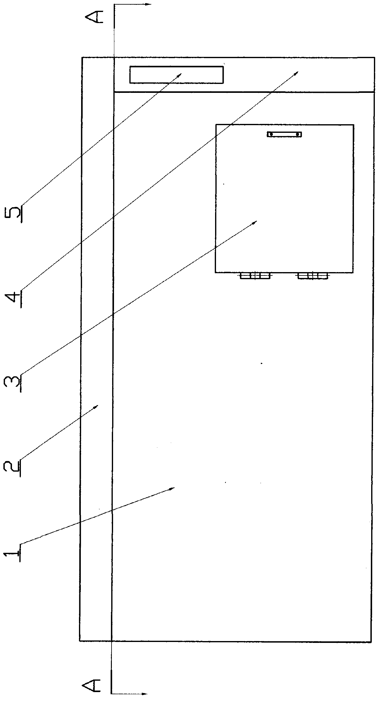
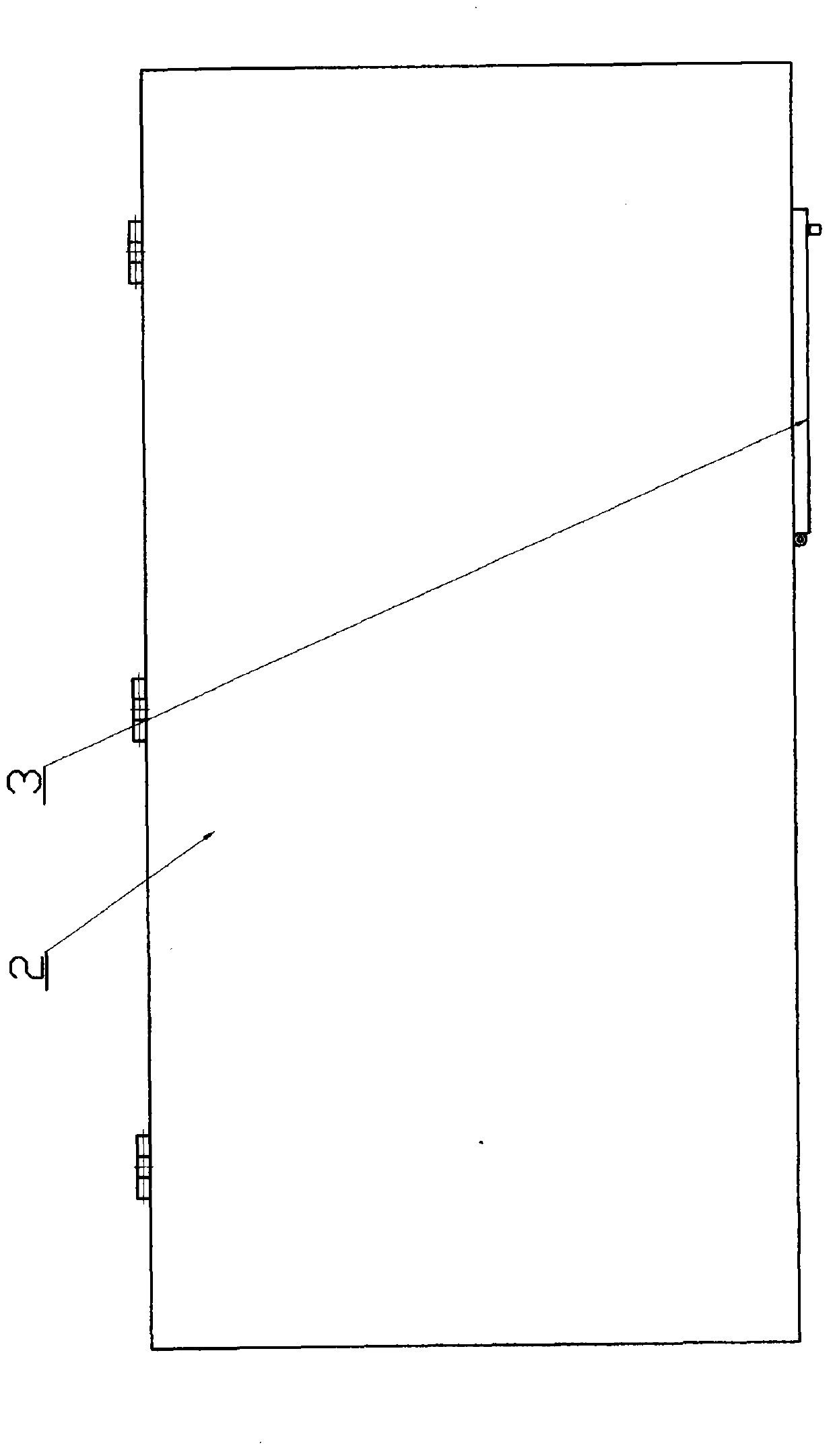
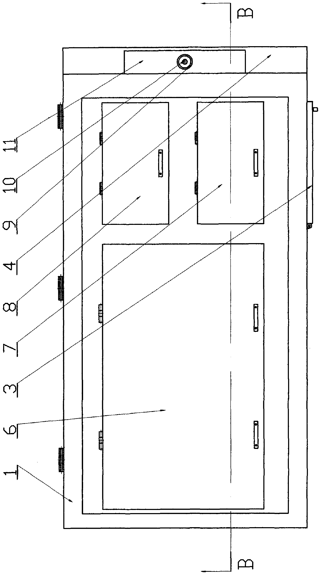
[0029] The present embodiment is made of kiln box body 1, kiln box cover 2 and control box 4, and kiln box body 1 and control box 4 are installed side by side, and kiln box cover 2 is installed above it.
[0030] The kiln box body 1 is a hollow box body in a rectangular parallelepiped, and its inner chamber is divided into left and right parts. The left part (usually accounting for more than half of the whole space) is the main kiln chamber 27, and the right part is the auxiliary kiln chamber 17, forming the main kiln chamber 17. Kiln chamber 27 and auxiliary kiln chamber one 17 two workrooms; If main kiln chamber 27 is arranged on the right part, auxiliary kiln chamber one 17 is arranged on the left part, then constitute an equivalent body of the present invention.
[0031] Above the main kiln chamber 27, the main kiln chamber cover 6 is hinged, and the main kiln chamber thermocouple 12 is also installed on the inner surface of the main kiln chamber cover 6; It is set to one ...
Embodiment 2
[0041] This embodiment is a variation of Embodiment 1, which is improved on the basis of Embodiment 1. It differs from Embodiment 1 in that: the inner cavity of the kiln box body 1 is divided into two parts, the left part (usually accounting for the entire More than half of the space) is the main kiln chamber 27, and the right part is divided into the front auxiliary kiln chamber 17 and the rear auxiliary kiln chamber 30, forming the main kiln chamber 27, auxiliary kiln chamber 1 17 and auxiliary kiln chamber 2 30 studio.
[0042] Auxiliary kiln chamber two covers 8 are installed (or hinged) on the auxiliary kiln chamber two 30, and in the inner cavity of auxiliary kiln chamber 30, two layers (can be set as one or two layers or three layers or four layers) are installed. Layer or more layers, this example is set as the second floor) auxiliary kiln chamber two partitions 31 (positioned by the triangular convex strips on the kiln wall), forming three layers of space for placing ...
Embodiment 3
[0049] This embodiment is another variation of Embodiment 1, which is improved on the basis of Embodiment 1. It differs from Embodiment 1 in that: the inner cavity of the kiln box body 1 is divided into two parts, left and right (usually Accounting for more than half of the whole space) is the main kiln chamber 27, the upper half of the right part is the auxiliary kiln chamber 17, and the lower half of the right part is the drying chamber 21, forming the main kiln chamber 27, auxiliary kiln chamber 17 and Three working chambers of drying chamber 21; if the upper half of the right part of the kiln casing 1 inner chamber is set as drying chamber 21, and the lower half of the right part is auxiliary kiln chamber 17, then constitutes another one of the present invention equivalent.
[0050] The front of the drying chamber 21 leads to the lower right part of the front of the kiln casing 1, and a drying chamber door 3 is hinged there; layer or two layers or three layers or four lay...
PUM
 Abstract
Description
Claims
Application Information
 - R&D
- Intellectual Property
- Life Sciences
- Materials
- Tech Scout
- Unparalleled Data Quality
- Higher Quality Content
- 60% Fewer Hallucinations
Browse by: Latest US Patents, China's latest patents, Technical Efficacy Thesaurus, Application Domain, Technology Topic, Popular Technical Reports.
© 2025 PatSnap. All rights reserved.Legal|Privacy policy|Modern Slavery Act Transparency Statement|Sitemap|About US| Contact US: help@patsnap.com


