

Method for determining sampling moment according to data receiving moment
A technology of sampling time and receiving time, applied in analog/digital conversion, instruments, signal transmission systems, etc., can solve problems such as large sampling time error
Active Publication Date: 2013-07-31
CHINA ELECTRIC POWER RES INST +3
View PDF3 Cites 9 Cited by
- Summary
- Abstract
- Description
- Claims
- Application Information
AI Technical Summary
Problems solved by technology
[0008] The sampling time calculated under this kind of jitter has a large error, and a method for determining the sampling time with high precision is urgently needed
Method used
View moreImage
Smart ImageViewing Examples

Examples
Embodiment
[0145] This method has been used in the measurement scheme of the phase difference of the merging unit at present, and the accuracy can reach 1us. Specific application see Figure 5 , Image 6 . Figure 5 The left side shows the results calculated by the conventional method measurement, Figure 5 What the right side shows is the result of measuring and calculating with this method, the left side and the right graph line compare and know, utilize the precision that the method for determining the sampling time according to the data receiving time provided by the present invention is high, and calculation is simple. Image 6 It is the waveform display of the data sent by merging unit 1, merging unit 2 and merging unit 3.
Login to View More PUM
 Abstract
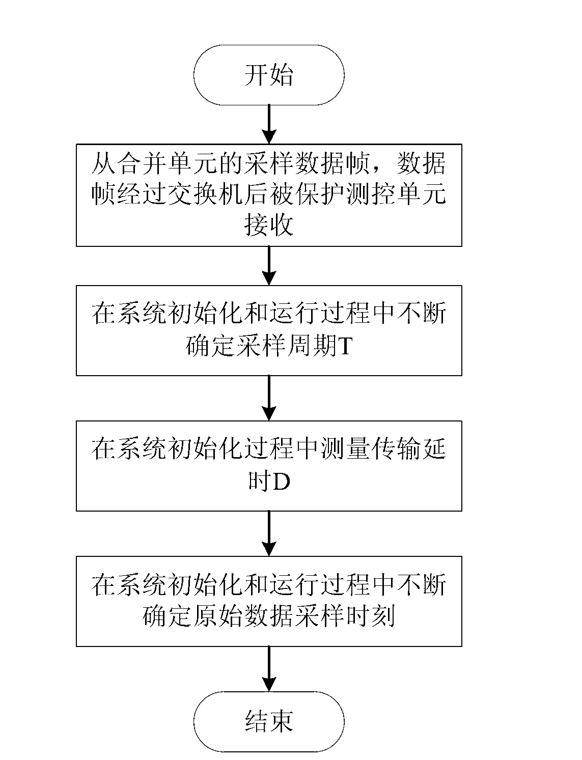
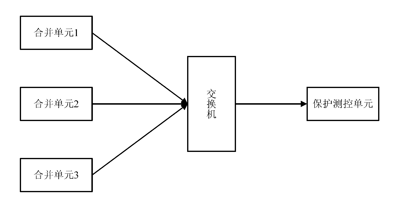
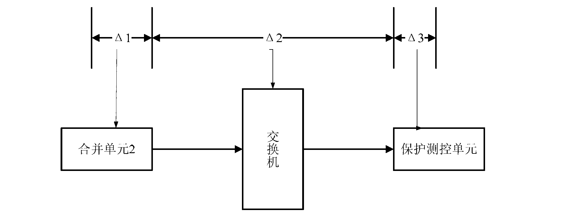
The invention relates to a method for determining a sampling moment according to a data receiving moment. A device adopted by the method comprises a merging unit, a switch and a protection and measure-control unit which are sequentially connected through optical fibers. Data sampling for the method is performed uniformly, and the method comprises the following steps: (1), sampling data frames from the merging unit, receiving the data frames by the protection and measure-control unit after the data frames pass through the switch; (2),determining a sampling period T continuously in system initialization and operation processes; (3),measuring transmission time delay D in a system initialization process; and (4), determining a sampling moment of raw data continuously in the system initialization and operation processes. According to the method, uncertainty of time delay of data transmission is eliminated; and further, the switch is adopted in a data transmission process, therefore, the complexity for fiber-optic link can be reduced, and the calculation accuracy of the sampling moment is high.
Description
technical field [0001] The invention relates to a method in the field of substation automation, in particular to a method for determining sampling time according to data receiving time. Background technique [0002] In the substation automation system with a three-tier architecture (process layer, interval layer, and station control layer), each data acquisition device (that is, the merging unit) is required to Sampling at all times (accurately speaking, it should be ensured that what is collected is the collected quantity that arrives at the input interface of the acquisition device at the same time. Since different devices have different delays from the input interface to the A / D conversion circuit, it is actually required that each A different device takes this delay into account when performing A / D conversion), so that the receiver of the sampling value frame can align the data collected by different merging units according to the sampling time as long as the smpcount in...
Claims
Login to View More Application Information
Patent Timeline
 IPC IPC(8): H03M1/54
Inventor李劲松吴晓博许智杨威瞿晓宏陆天健王化鹏刘筱萍刘洋陈心灿张金虎杨文平张海燕孟德伦李睿宜
OwnerCHINA ELECTRIC POWER RES INST