Automated identification of occlusion location in the culprit coronary artery

A coronary artery, occlusion technology, applied in the field of electrocardiograph system, can solve the problem of high risk of right ventricular infarction

Active Publication Date: 2013-07-31
KONINKLIJKE PHILIPS ELECTRONICS NV
View PDF8 Cites 1 Cited by
  • Summary
  • Abstract
  • Description
  • Claims
  • Application Information

AI Technical Summary

Problems solved by technology

Therefore, for proximal obstruction of the LAD, patients are in the highest risk category
Higher risk for righ

Method used


Image

  • Automated identification of occlusion location in the culprit coronary artery
  • Automated identification of occlusion location in the culprit coronary artery
  • Automated identification of occlusion location in the culprit coronary artery

Examples


Embodiment Construction

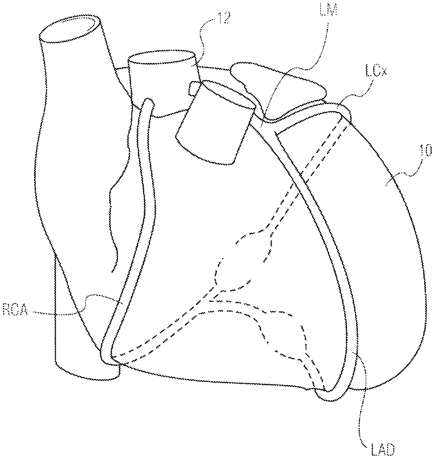
[0029] Figure 1 to Figure 3 Various views of the heart showing the location of the coronary arteries which, when blocked, can cause significant damage to the heart. figure 1 is a high-level schematic view showing the right coronary artery (RCA) descending from the aorta 12 along the right side of the heart 10 . Also descending from the aorta along the left side of the heart is the left main (LM) coronary artery, which soon branches to form the left anterior descending (LAD) artery in front of the heart (anterior) and wraps around the back of the heart (posterior ) of the left circumflex (LCx) artery. All three main vessels are shown in characteristic tortuous paths that eventually wrap around the heart 10 to provide a constant supply of fresh blood to the myocardium.

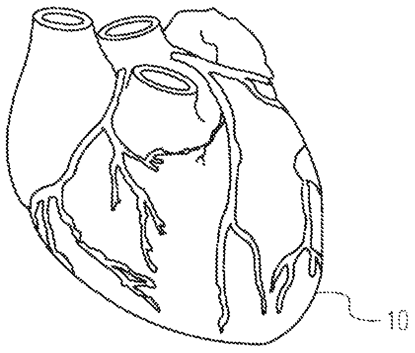
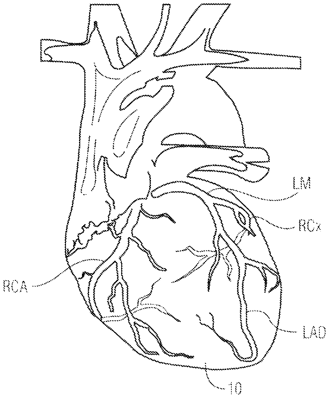
[0030] figure 2 The same arteries and branches are shown from the front side of the heart 10 in a more anatomically correct depiction of the heart. image 3 In , the heart 10 is depicted as a translucent s...


PUM


Abstract

A diagnostic ECG system analyzes lead traces for evidence of ST elevation in the lead signals. The pattern of ST elevation in leads having predetermined vantage points to the electrical activity of the heart and, in some instances, the presence of ST depression in certain other leads, identifies a specific coronary artery or branch as the culprit coronary artery for an acute ischemic event. ECG measurements which are associated with the identity of specific arterial occlusion locations are calculated and used to form a classifier of the probability of occlusion at different locations. The location identified as having the highest probability is indicated to a user as the most likely occlusion location.

Description

technical field [0001] The present invention relates to an electrocardiograph system, and, in particular, to an electrocardiograph system for automatically identifying the location of an occlusion in an incident coronary artery causing acute myocardial infarction. Background technique [0002] Electrocardiography (ECG) is widely used to generate recordings derived from voltages produced by the heart on the surface of the body. The records thus produced are graphical in nature and require expert interpretation and analysis to correlate the resulting information to the patient's cardiac condition. Historically, such recordings have been generated as visual graphical recordings directly from a wired connection extending from the subject to the recording device. Advances in computer technology have made it possible to produce such records in the form of digitally stored information for later reproduction and analysis. [0003] A crucial urgent clinical application of ECG recor...

Claims


Application Information

Patent Timeline
IPC IPC(8): A61B5/0452A61B5/04A61B5/364A61B5/366
CPCA61B5/02007A61B5/04012A61B5/0452A61B5/0468A61B5/316A61B5/349A61B5/364
Inventor R·格雷格S·H·周C-H·陈
Owner KONINKLIJKE PHILIPS ELECTRONICS NV
Why Eureka
Try Eureka