
Crankshaft positioning pin pressing-mounting tool

A technology of press-fitting tooling and positioning pins, which is applied in metal processing, manufacturing tools, metal processing equipment, etc., can solve the problems of high labor intensity, difficult to ensure the quality of press-fitting, and easy damage to the roundness of the outer circular surface of the crankshaft. The effect of low labor intensity, ensuring the quality of pressing and reducing the requirements of manual skills

Active Publication Date: 2013-08-07
长城汽车股份有限公司平湖分公司
View PDF4 Cites 11 Cited by
  • Summary
  • Abstract
  • Description
  • Claims
  • Application Information

AI Technical Summary

Problems solved by technology

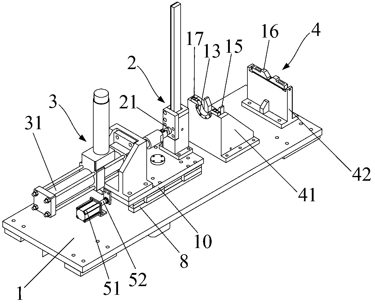
[0006] The invention provides a positioning pin press-fitting tool, which uses a press-fit piston cylinder instead of manpower, and sets a guide mechanism for supporting the press-fit piston cylinder piston rod between the press-fit piston cylinder and the crankshaft, so that the press-fit piston cylinder The piston rod presses the positioning pin along the axis of the crankshaft pin hole to solve the problems that the roundness of the outer surface of the crankshaft is easily damaged when the positioning pin is manually pressed, the quality of the pressing is difficult to guarantee, and the labor intensity is high.

Method used


Image

  • Crankshaft positioning pin pressing-mounting tool
  • Crankshaft positioning pin pressing-mounting tool
  • Crankshaft positioning pin pressing-mounting tool

Examples


Embodiment Construction

[0020] The specific implementation manners of the present invention will be further described in detail below in conjunction with the accompanying drawings and embodiments. The following examples are used to illustrate the present invention, but are not intended to limit the scope of the present invention.

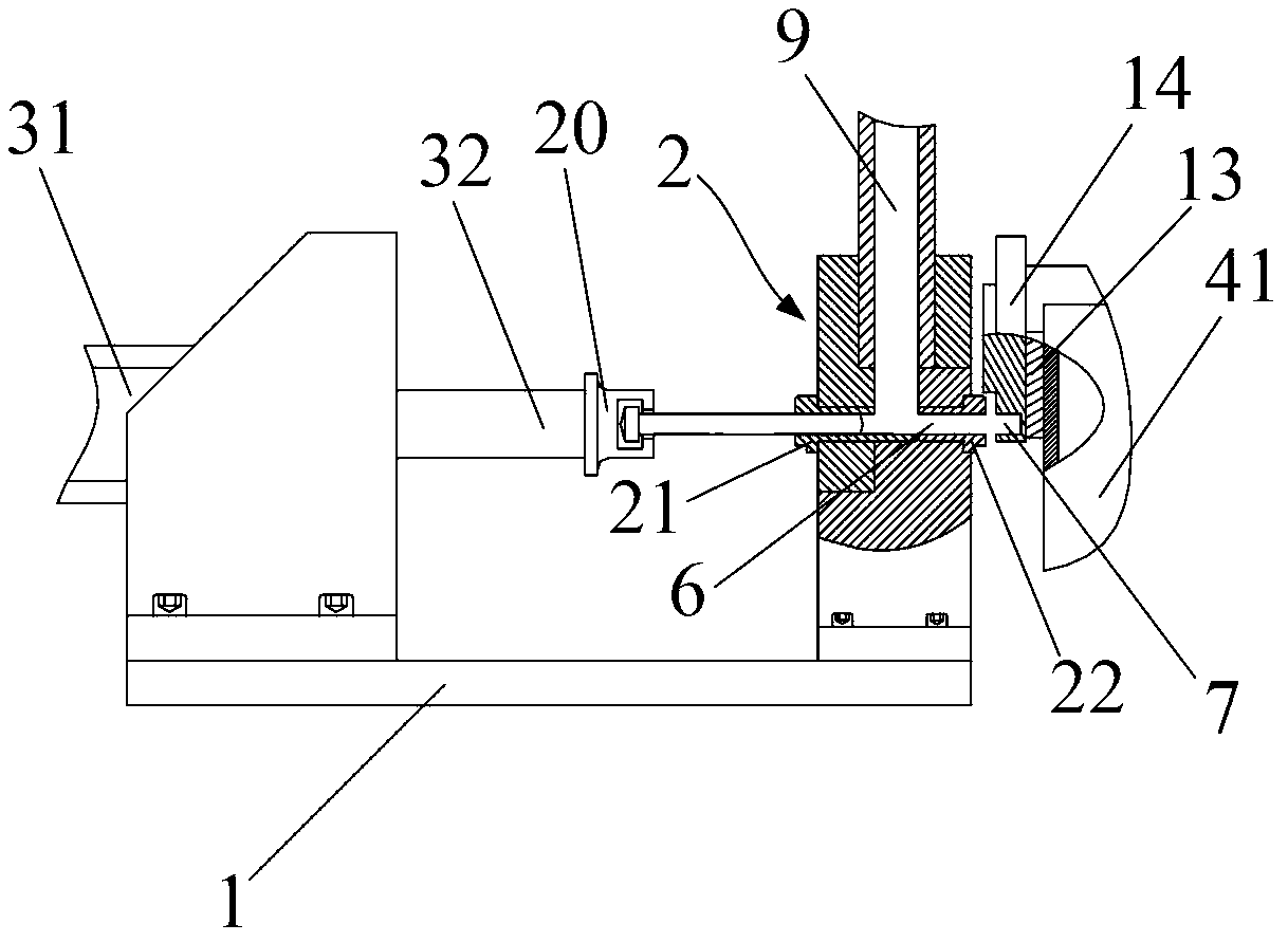
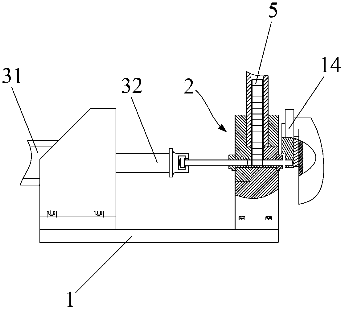
[0021] figure 1 Shown is a schematic structural view of the positioning pin press-fitting tooling in the embodiment of the present invention; Figure 2.1 , Figure 2.2 and Figure 2.3 It is a schematic diagram of the process of press-fitting the positioning pin by the positioning pin pressing tool in the embodiment of the present invention. combine figure 1 , Figure 2.1 , Figure 2.2 and Figure 2.3 As shown, the positioning pin pressing tooling in the embodiment of the present invention includes a guiding mechanism 2 , a pressing mechanism 3 and a fixing mechanism 4 . Wherein, the press-fit mechanism 3 includes a press-fit piston cylinder 31, which is used to pro...


PUM


Abstract

The invention relates to the technical field of automobile production tools and discloses a crankshaft positioning pin pressing-mounting tool. The crankshaft positioning pin pressing-mounting tool comprises a guiding mechanism, a pressing-mounting mechanism and a fixing mechanism, wherein the pressing-mounting mechanism comprises a pressing-mounting piston cylinder and is used for substituting for manpower and providing pressing-mounting force, accordingly the requirements for manual skills are reduced, and labor intensity is reduced. A guiding through hole is arranged on the guiding mechanism and is matched with a piston rod of the pressing-mounting piston cylinder to enable the piston rod of the pressing-mounting piston cylinder to perform reciprocating motion on one straight line and not to be influenced by self weight. When a positioning pin is pressed and mounted, a crankshaft is fixedly placed on the fixing mechanism. The guiding mechanism is installed between the fixing mechanism and the pressing-mounting mechanism to enable the piston rod of the pressing-mounting piston cylinder to press the positioning pin into a pin hole along the axis direction of the pin hole, the roundness of an excircle face of a crankshaft flange is not damaged, and the pressing-mounting quality of the crankshaft positioning pin is ensured.

Description

technical field [0001] The invention relates to the technical field of automobile production tooling, in particular to a crankshaft positioning pin press-fitting tooling. Background technique [0002] The car engine outputs the torque required by the car through the crankshaft flywheel set, which is mainly composed of the crankshaft and the flywheel. The crankshaft is the main rotating mechanism of the automobile engine. It is used to convert the up and down reciprocating motion of the piston into the circular motion of the crankshaft itself, so as to output torque for the driving of the car. The engine speed is usually the speed of the crankshaft; Connection, used to store energy to overcome the resistance of the non-power stroke, so that the engine runs smoothly. [0003] In the prior art, the mutual positions of the crankshaft flange and the flywheel are accurately positioned by means of crankshaft positioning pins, so as to realize the fixed connection between the flywh...

Claims


Application Information

Patent Timeline
Patent Type & Authority Applications(China)
IPC IPC(8): B23P19/12
Inventor 李刚蒋志伟赵红俊
Owner 长城汽车股份有限公司平湖分公司
Learn More