
Cuttings collecting device with auger mechanism

A collection device and cutting chip technology are applied to cleaning methods and tools, metal processing machinery parts, and dust removal. The effect of improving safety

Inactive Publication Date: 2013-08-07
四川东方能源科技股份有限公司
View PDF5 Cites 0 Cited by
  • Summary
  • Abstract
  • Description
  • Claims
  • Application Information

AI Technical Summary

Problems solved by technology

[0004] The purpose of the present invention is to overcome the deficiency that the existing technology cannot fundamentally solve the problem of chip accumulation, and to provide a chip collection device using an auger mechanism

Method used

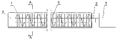
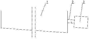

Image

  • Cuttings collecting device with auger mechanism
  • Cuttings collecting device with auger mechanism
  • Cuttings collecting device with auger mechanism

Examples


Embodiment 1

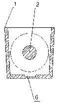
[0031] Such as figure 1 As shown, the chip collection device using the auger mechanism includes a housing 1, an auger shaft 2, a driving motor 3 and a fixed body 4, and the housing 1 is arranged on both sides of the milling machine platform. Such as image 3 As shown, the radial section of the housing 1 is U-shaped. Both ends of the casing 1 are open, the fixed body 4 is arranged at one end of the casing 1, the auger shaft 2 is arranged in the casing 1, one end of the auger shaft 2 is fixed on the fixed body 4 in rotation, the other end of the auger shaft 2 One end protrudes from the end of the housing 1 without the fixed body 4 and is connected to the output shaft of the driving motor 3 , there is a gap between the driving motor 3 and the housing 1 .

[0032] The driving motor 3 drives the auger shaft 2 to rotate, thereby taking away the cutting chips falling in the housing 1 , and the cutting chips fall out from the gap between the housing 1 and the driving motor 3 . This...

Embodiment 2

[0034] Such as image 3 As shown, in this embodiment, on the basis of the above-mentioned embodiments, the two sides of the housing 1 are inclined outwards, so that the housing 1 has a structure that is wide at the top and narrow at the bottom, which is more conducive to cutting chips entering the housing 1. Prevent cutting chips from accumulating on the edge of the housing 1.

Embodiment 3

[0036] Such as figure 1 As shown, this embodiment further includes a fence 5 on the basis of the above embodiments, and the fence 5 is arranged on the top of the housing 1 . The fence 5 can prevent workers from stepping into the housing 1 by mistake, which improves the safety of this embodiment.


PUM


Abstract

The invention discloses a cuttings collecting device with an auger mechanism. The cuttings collecting device comprises a shell (1), an auger shaft (2), a driving motor (3) and a fixer (4), the shell (1) is arranged on two sides of a milling machine platform, the radial section of the shell (1) is U-shaped, two ends of the shell (1) are open, the fixer (4) is arranged at one end of the shell (1), the auger shaft (2) is arranged in the shell (1), one end of the auger shaft (2) is rotatably fixed on the fixer (4), the other end of the auger shaft (2) extends out of the end without the fixer (4) on the shell (1) and is connected with an output shaft of the driving motor (3), and a gap is reserved between the driving motor (3) and the shell (1). The cuttings collecting device has the advantages that the cuttings collecting device overcomes the shortcoming that the problem of cuttings accumulation cannot be fundamentally solved in the prior art, manpower intervention is omitted in the whole process, two sides of a milling machine can be constantly kept clean and tidy, and the influence of cuttings accumulation on normal machining is avoided.

Description

technical field [0001] The invention relates to the field of milling, in particular to a chip collecting device using an auger mechanism for a milling machine. Background technique [0002] During the working process of the milling machine, especially for the milling process of large workpieces, a large amount of cutting chips will be generated. If the cutting chips are not cleaned, a large amount of cutting chips will accumulate on both sides of the milling machine, which will hinder normal processing. [0003] At present, the more commonly used method is to set chip collection grooves on both sides of the milling machine, and the chips generated during the milling process will fall into the chip collection grooves, and then be cleaned manually. The disadvantage of this approach is that it still relies on manpower and requires staff to monitor the accumulation of cutting chips. If there is no control for a long time, it will still affect normal processing. Therefore, the ...

Claims


Application Information

Patent Timeline
IPC IPC(8): B23Q11/00B08B15/00
Inventor 王曾勇叶礼
Owner 四川东方能源科技股份有限公司
Learn More