
Electronic injection motorcycle idling air compensating valve mounting structure

A technology of installation structure and air supply valve, which is applied to bicycle accessories, transportation and packaging, gasoline barrels, etc., can solve the problems of difficulty in the installation of air supply passages, affect the efficiency of engine air supply, and affect the air-fuel ratio of the engine, etc., to achieve favorable Installation operation, simple installation, low cost effect

Active Publication Date: 2013-08-07
力帆科技(集团)股份有限公司
View PDF4 Cites 1 Cited by
  • Summary
  • Abstract
  • Description
  • Claims
  • Application Information

AI Technical Summary

Problems solved by technology

[0003] 1) The air supply path is long, which will affect the air supply efficiency of the engine;
[0004] 2) The air supply passage is located under the fuel tank, and the space in this part is small, the arrangement and installation of the air supply passage is difficult, and the assembly efficiency is not high;
[0005] 3) The intake hose and outlet hose of the idle air supply valve pass above the engine cylinder head. Due to the high temperature of the engine cylinder head and the influence of heat radiation, the temperature of the air supplied to the engine through the hose is higher than the atmospheric temperature , which will cause the ECU to misjudge the intake air volume, thus affecting the air-fuel ratio of the engine;
[0006] 4) The assembly of the idling air supply valve requires multiple accessories such as brackets and clips, and the production cost is relatively high

Method used


Image

  • Electronic injection motorcycle idling air compensating valve mounting structure
  • Electronic injection motorcycle idling air compensating valve mounting structure
  • Electronic injection motorcycle idling air compensating valve mounting structure

Examples


Embodiment Construction

[0019] Below in conjunction with accompanying drawing and embodiment the present invention will be further described:

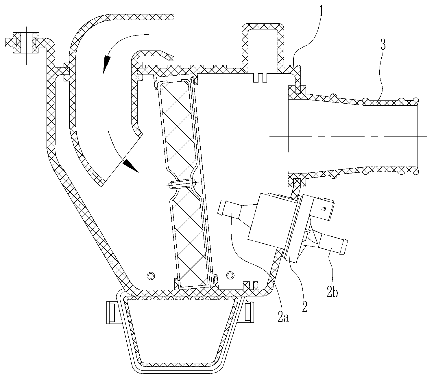
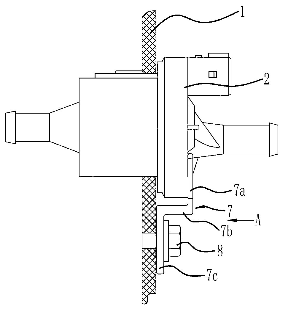
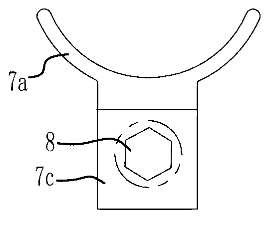
[0020] Such as figure 1 , figure 2 , image 3 As shown, the present invention is made up of air filter 1, idling air supply valve 2, throttle connecting pipe 3 and support 7 etc., the upper part of air filter 1 front end wall is equipped with throttle connecting pipe 3, the structure of throttle connecting pipe 3 And the installation method is the same as the prior art, and will not be repeated here. There is an installation hole at the bottom of the front end wall of the air filter 1, the main body of the idle air supply valve 2 is put into the installation hole, and the main body of the idle air supply valve 2 is fixed to the front end wall of the air filter 1 by sealant, The stepped surface on the main body of the idle air supplement valve 2 is in close contact with the front end surface of the air filter 1 . The idle air supply valve 2 is arranged w...


PUM


Abstract

The invention discloses an electronic injection motorcycle idling air compensating valve mounting structure which comprises an air filter (1) and an idling air compensating valve (2). An air throttle connecting pipe (3) is mounted on the front end wall of the air filter (1), the idling air compensating valve (2) is positioned below the air throttle connecting pipe (3) and is mounted on the front end wall of the air filter (1) in an embedded manner and is tightly compressed and positioned by a support (7), an air inlet nozzle (2a) of the idling air compensating valve (2) is positioned inside the air filter (1), and an air outlet nozzle (2b) of the idling air compensating valve (2) is positioned outside the air filter (1). The idling air compensating valve is directly mounted on the air filter and is simple and convenient to mount and fine in reliability, an air compensating passage is greatly shortened, the air compensating efficiency of an engine is improved, and the mounting structure has the advantages of reasonable design, easiness in implementation, low improvement cost and the like, and is applicable to various electronic injection motorcycles.

Description

technical field [0001] The invention belongs to the technical field of motorcycles, and in particular relates to an installation structure of an idle air supply valve of an electric jet motorcycle. Background technique [0002] The idle air supply valve is an important part of the EFI motorcycle, which is used to supplement the fresh air in the air filter into the engine. Such as Figure 4 As shown, the intake nozzle 2a of the idle air supplement valve 2 is connected to the joint 5 on the air filter 1 through the intake hose 4, and the air outlet nozzle 2b of the idle air supplement valve 2 is connected to the engine through the air outlet hose 6. The idling air supply valve 2 is located between the air filter 1 and the engine, and is fixed to the vehicle frame through a mounting bracket and two mounting clips. The disadvantages of the above structure are: [0003] 1) The air supply path is long, which will affect the air supply efficiency of the engine; [0004] 2) The a...

Claims


Application Information

Patent Timeline
IPC IPC(8): B62J37/00
Inventor 马文选
Owner 力帆科技(集团)股份有限公司
Learn More