Device and method for testing adhesive property between fiber reinforce plastic (FRP) rib and concrete under complicated stress state

A technology of stress state and testing device, which is applied in the direction of measuring device, mechanical device, instrument, etc., to achieve the effect of simple device and convenient operation

Active Publication Date: 2014-11-19
王亚军
View PDF7 Cites 0 Cited by
  • Summary
  • Abstract
  • Description
  • Claims
  • Application Information

AI Technical Summary

Problems solved by technology

[0006] The purpose of the present invention is to design a device capable of simulating the actual stress state in view of the fact that the existing test device can only perform FRP bars and concrete bonding performance tests without external loads and the actual situation. Test device for bonding performance between FRP bars and concrete under complex stress conditions, and propose corresponding test methods

Method used


Image

  • Device and method for testing adhesive property between fiber reinforce plastic (FRP) rib and concrete under complicated stress state
  • Device and method for testing adhesive property between fiber reinforce plastic (FRP) rib and concrete under complicated stress state
  • Device and method for testing adhesive property between fiber reinforce plastic (FRP) rib and concrete under complicated stress state

Examples


Embodiment 1

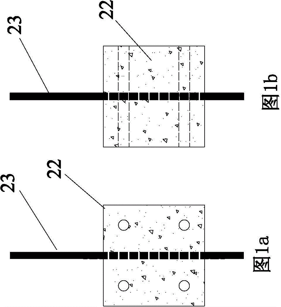
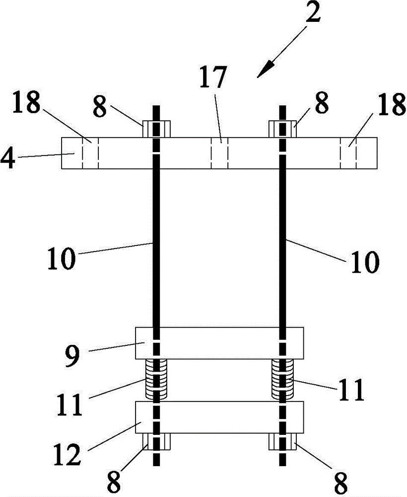
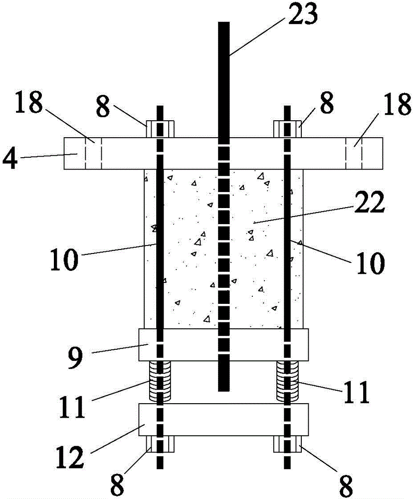
[0049] Such as Figure 1-12 shown.

[0050] A device for testing the bonding performance of FRP bars and concrete under complex stress conditions, which includes a vertical outer frame 1 ( Figure 7 ), vertical inner frame 2 ( figure 2 ) and horizontal frame 3 ( Figure 4 ), Specimen 22 ( figure 1 ) clamp the horizontal frame 3 and then clamp it in the vertical inner frame 2, and then clamp the vertical inner frame 2 in the vertical outer frame 1, and the FRP ribs 23 of the test piece 22 pass through the top plate of the vertical outer frame 1 Link to each other with tensile testing machine afterward, the bottom tie rod 7 of vertical outer frame 1 lower end also links to each other with tensile testing machine, and the stressed direction of specimen 22 and bottom tie bar 7 is opposite. The vertical outer frame 1 ( Figure 7 ) includes a top steel plate 4, a first vertical column steel rod 5, a first bottom steel plate 6 and a bottom tie rod 7, and the first vertical ...

Embodiment 2

[0056] The invention discloses a method for testing the bonding performance of FRP tendons and concrete under complex stress conditions, which is characterized in that it includes the preparation of specimens, clamping and tensile testing.

[0057] The preparation method and steps of the test piece are as follows:

[0058] First of all, prepare for the trial mold, set a round hole in the center of the front and rear side templates of the trial mold, for passing through the FRP bars, and set four round holes at the four corners of the left and right side molds for the test mold Wear 4 PVC pipes and form reserved holes after concrete pouring. The reserved holes are used to pass through the 4 horizontal steel rods 15 of the horizontal frame 3. The purpose is to facilitate the simultaneous installation of the vertical inner frame and the horizontal frame, such as figure 1 and Figure 6 ;

[0059] Second, after fixing the FRP bars and PVC pipes in the side mold holes of t...


PUM


Abstract

The invention relates to a device and a method for testing the adhesive property between a fiber reinforce plastic (FRP) rib and concrete under a complicated stress state. The device is characterized by comprising a vertical outer frame (1), a vertical inner frame (2) and a transverse frame (3); after being clamped by the transverse frame (3), a test piece (22) is clamped in the vertical inner frame (2); the vertical inner frame (2) is then clamped in the vertical outer frame (1); the FRP rib (23) of the test piece (22) passes through a top plate of the vertical outer frame (1) and is then connected with a tensile testing machine; a bottom pull rod (7) arranged at the lower end of the vertical outer frame (1) is connected with the tensile testing machine; and the stress direction of the test piece (22) is opposite to that of the bottom pull rod (7). The device and the method are simple and practicable, and an ideal experimental device is provided for the pull-out test in the complicated stress state.

Description

technical field [0001] The invention relates to a technology for testing the stress of building components, in particular to a technology for testing the bond performance of FRP bars and concrete, specifically a method for bonding FRP bars and concrete under complex stress conditions that can simulate actual stress conditions Method and apparatus for performance pull-out test. Background technique [0002] Corrosion of steel bars is the main factor affecting the structural loss of bearing capacity and the expected service life, and it is also an important issue affecting the durability of reinforced concrete structures. FRP bars are made of continuous fiber (glass fiber, carbon fiber, aramid fiber, hybrid fiber) as reinforcement material, synthetic resin as matrix material, mixed with appropriate amount of auxiliary agent, and formed by pultrusion technology and necessary surface treatment. A new type of composite material. Compared with traditional steel bars, it has the ...

Claims


Application Information

Patent Timeline
Patent Type & Authority Patents(China)
IPC IPC(8): G01N19/04
Inventor 陈育志宣卫红陈晓洪
Owner 王亚军
Why Eureka
Try Eureka