Eureka AIR delivers breakthrough ideas for toughest innovation challenges, trusted by R&D personnel around the world.

Debugging device applied to pairing of negative control terminal and ammeter

A technology of negative control terminals and electric meters, which is applied in the field of paired debugging devices between negative control terminals and electric meters, which can solve problems such as power consumption, debugging danger, and metering circuit wiring errors

Inactive Publication Date: 2013-08-07
STATE GRID CORP OF CHINA +1
View PDF10 Cites 4 Cited by
  • Summary
  • Abstract
  • Description
  • Claims
  • Application Information

AI Technical Summary

Problems solved by technology

[0005] 2. The metering devices of some users are installed on poles and iron towers, which are close to high-voltage lines. On-site live debugging is more dangerous and may easily cause safety accidents
[0006] 3. The load control terminal and the electric energy meter are connected in parallel. If the debugging is unsuccessful, the terminal needs to be disassembled repeatedly, which is prone to errors in the wiring of the metering circuit.
[0007] 4. On-site debugging requires the cooperation of personnel from multiple departments. The door of the metering box and the tail of the electric energy meter need to be unsealed, which leads to a lot of waste of sealed lead
[0008] 5. For users who cannot send power in time for new installations, the commissioning personnel must wait for the on-site power transmission before performing terminal debugging after the on-site installation is completed, and it will be time-consuming and labor-intensive to repeatedly go to the site to work

Method used


Image

  • Debugging device applied to pairing of negative control terminal and ammeter
  • Debugging device applied to pairing of negative control terminal and ammeter

Examples


Embodiment Construction

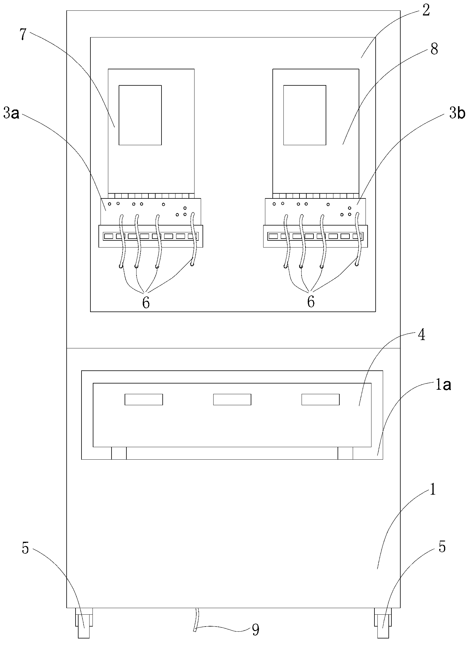
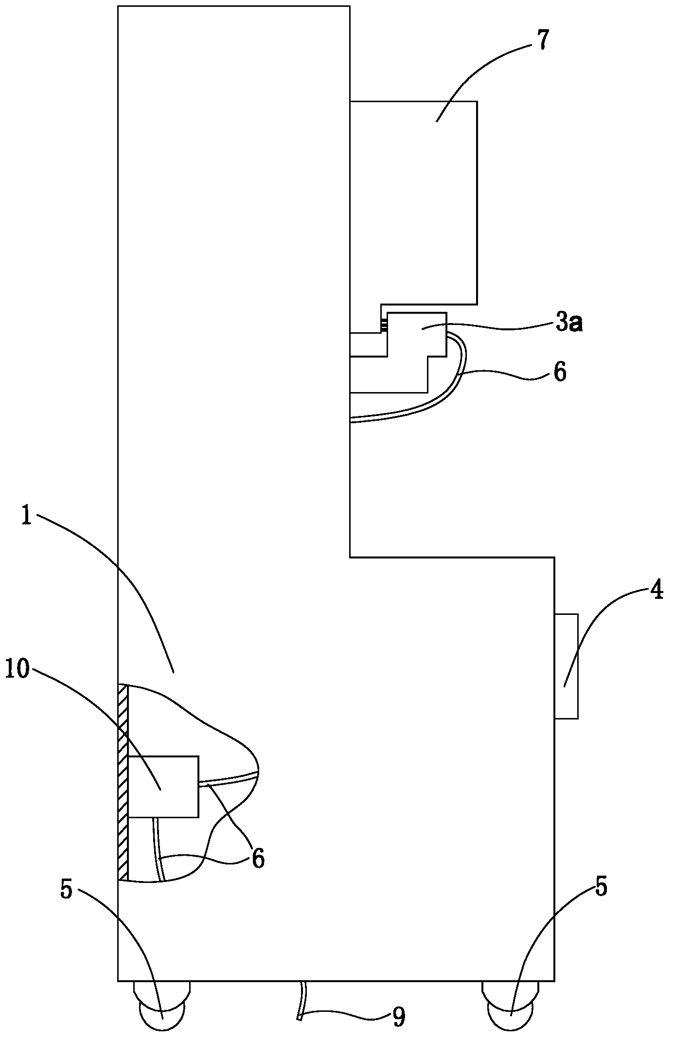
[0017] Such as Figures 1 to 2 As shown, the cabinet bracket 1 of this device is made of stainless steel, and the upper surface of the bracket 1 has a mounting plate 2 made of epoxy resin, and the two connecting brackets fixed by bolts in the middle of the mounting plate 2 are the first connecting bracket 3a and the second meter connection frame 3b.

[0018] There is a groove 1a in the middle of the bracket 1, and an electric meter calibrator 4 is placed in the groove 1a, and a leakage protector 10 is also installed in the bracket 1.

[0019] The first meter connection frame 3a and the second meter connection frame 3b are connected by wire 6 to realize the voltage parallel connection between the first meter connection frame 3a and the second meter connection frame 3b, and the first meter connection frame 3a and the electric meter calibrator 4 are connected by wire 6 to realize current series connection and voltage parallel connection between the electric meter calibrator 4 an...


PUM


Abstract

The invention provides a debugging device applied to the pairing of a negative control terminal and an ammeter. In the debugging device, an ammeter calibration instrument is arranged in a support, a mounting plate is arranged in the surface of the support and is fixedly connected with two ammeter connection frames, namely a first ammeter connection frame and a second ammeter connection frame, and the first ammeter connection frame is respectively connected with the second ammeter connection frame and an ammeter calibration instrument; an ammeter to be debugged and the negative control terminal are fixedly arranged on the mounting plate of the support, the first ammeter connection frame is provided with the ammeter, the second ammeter connection frame is provided with the negative control terminal, the first ammeter connection frame, the second ammeter connection frame and the ammeter calibration instrument are connected by conductors, and the ammeter calibration instrument is connected with a power supply. According to the debugging device applied to the pairing of the negative control terminal and the ammeter, disclosed by the invention, by regulating the current of the ammeter calibration instrument, the regular use states of the ammeter and the negative control terminal are simulated, the regular functions of the ammeter and the ammeter calibration instrument are tested, the working time and the working load of a repeated field debugging operation are reduced, and the terminal on-line rate is improved.

Description

technical field [0001] The invention relates to a device for pairing and debugging a load control terminal and an electric meter. Background technique [0002] The load control terminal is the equipment used by the power supply department to monitor and control the electricity consumption of the power consumption unit. The power supply department can directly notify the power consumption unit to carry out load control. When an instruction is issued, the user's load device immediately disconnects the user's main switch, and the load device uses radio to receive the signal from the power supply bureau; when the regional power load supply is tight, the power supply company can implement regional or industrial load regulation authorized by the government to ensure the critical load. And residential electricity consumption, when in use, the negative control terminal is used in conjunction with the ammeter. [0003] In recent years, with the rapid development and advancement of n...

Claims


Application Information

Patent Timeline
IPC IPC(8): G01R31/02
Inventor 梅开锋施培环冯爱国沈朝春张瑜张爱芳孙诚晨杨爽洁宋育芳杨伟伟
Owner STATE GRID CORP OF CHINA
Why Eureka
Eureka Blog
Learn More